Bumper system

a bumper system and bumper technology, applied in the field of bumpers, can solve the problems of considerable additional cost of providing bumper systems with attachment means for towing hooks, and achieve the effects of reducing the number of parts and production steps, reducing costs, and improving the transmission of tensile forces

Active Publication Date: 2006-11-16
CONSTELLIUM SWITZERLAND
View PDF5 Cites 17 Cited by
  • Summary
  • Abstract
  • Description
  • Claims
  • Application Information

AI Technical Summary

Benefits of technology

[0037] The integration of the attachment means, in particular the internal thread, in the connecting element results in better transmission of the tensile forces into the vehicle structure during a towing operation. The arrangement of the attachment means according to the invention is also robust with respect to a tensile force applied at a large angle to the longitudinal direction of the vehicle. Working the internal thread into a cylindrical hollow chamber in the connecting element also results in a reduction in the number of parts and the number of production steps. In particular manual operations such as welding or incorporation of pre-made sleeves in the bumper or on connecting elements can be replaced by automated production steps such as chip-forming processes. Both effects lead to a reduction in costs.

Problems solved by technology

In both cases, providing the bumper system with an attachment means for a towing hook involves considerable additional expense as the inner thread has to be created in separate working steps, often by hand e.g. by welding.

Method used


Image

  • Bumper system
  • Bumper system
  • Bumper system

Examples


Embodiment Construction

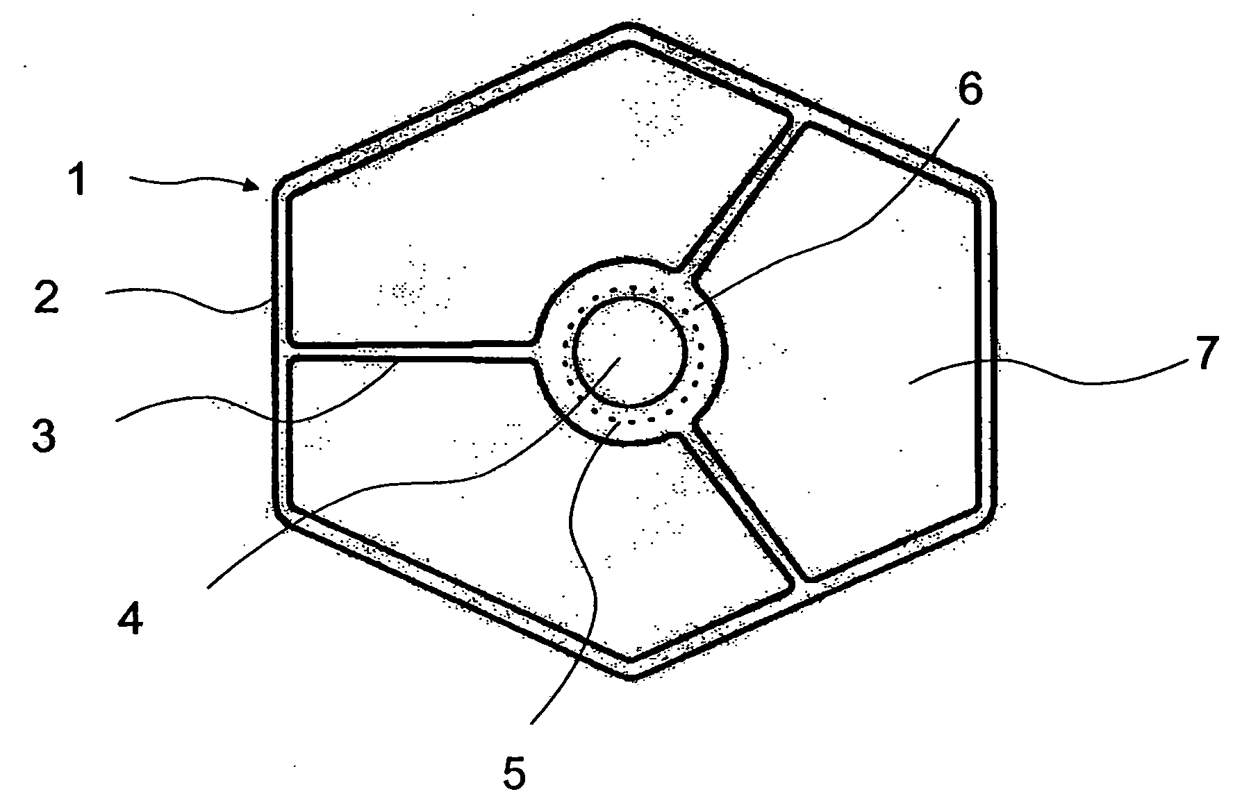
[0045]FIG. 1 shows a first version of a connecting element 1 according to the invention with a hexagonal cross-section. The connecting element 1 is a multi-chamber hollow section with four hollow chambers 4, 7. It contains outer section walls 2 and one central, cylindrical hollow chamber 4 formed by an inner section wall 6. The hollow chamber 4 is connected to the outer section walls 2 by connecting struts 3. The connecting struts 3 run essentially radially from the central hollow chamber 4 outwards to the outer section walls 2.

[0046] The broken line 5 outlines the inner circumference of the hollow chamber 4 after removing part of the wall thickness of the inner section wall preceding—in the direction of screwing in the towing hook—the internal thread. The internal thread (not shown) of the attachment means is worked into the inner section wall 6 in a later, chip-forming process.

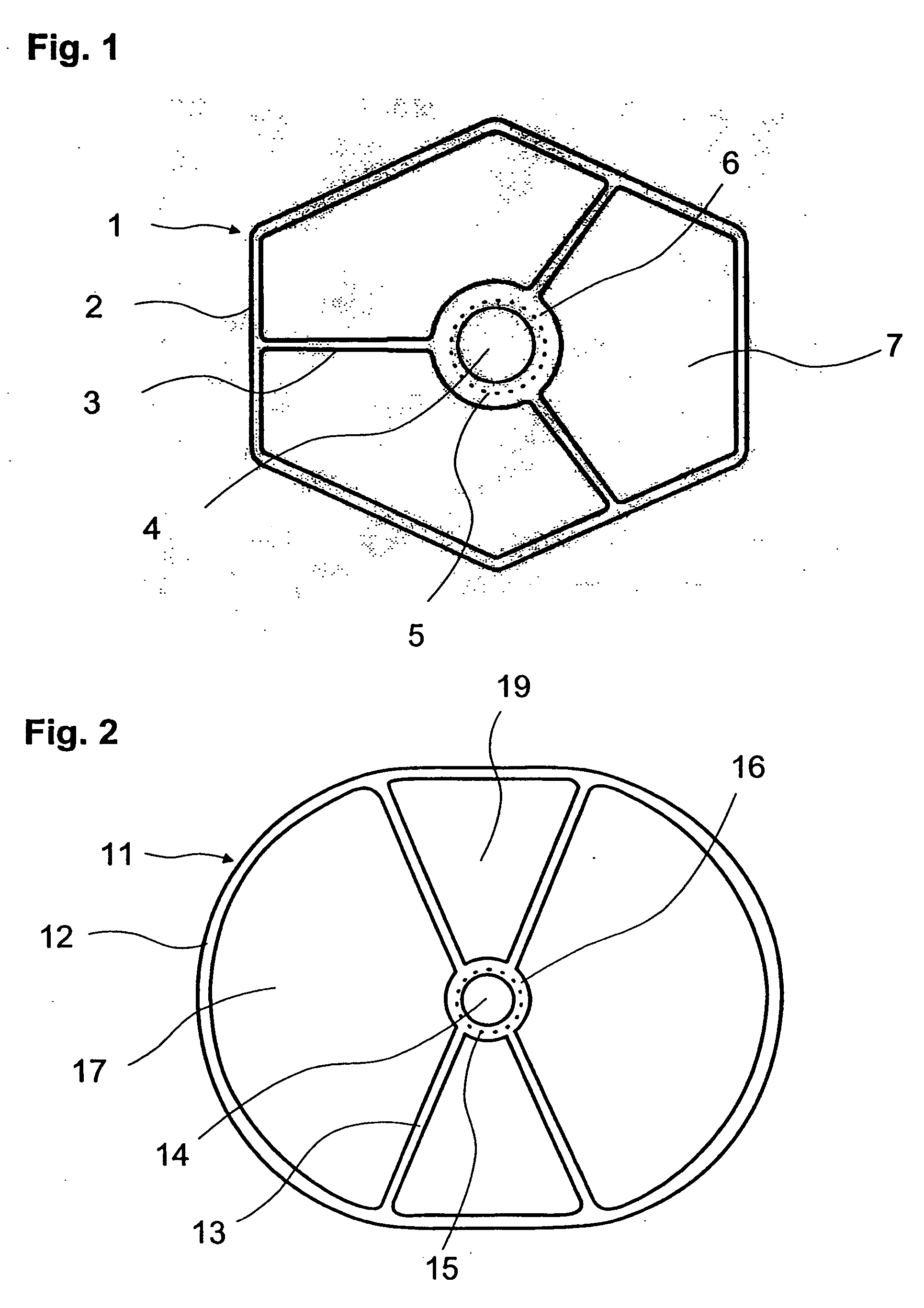
[0047]FIG. 2 shows a second version of a connecting element 11 according to the invention having a roun...


PUM


Abstract

A bumper system having a bumper running transverse to the longitudinal direction of a vehicle and at least one connecting element mounted thereon for the purpose of attaching the bumper to a vehicle, in particular to a longitudinal beam of a passenger car. The connecting element is a multi-chamber extruded section of metal with longitudinal axis running in the longitudinal direction of the vehicle. The connecting element is in the form of a safety element which, under impact, absorbs impact energy by compressive deformation. For the purpose of connecting a towing device, an attachment member is provided that is situated in one of the hollow chambers of the connecting element.

Description

BACKGROUND OF THE INVENTION [0001] The present invention relates to a bum per system containing a bumper running transverse to the longitudinal direction of a vehicle, a connecting element on the bumper for attaching the bumper to a vehicle, in particular onto the longitudinal beam of a passenger car, and attachment means for mounting a releasable towing facility. The connecting element is a multi-chamber extruded section of metal having a longitudinal axis (x) lying in the longitudinal direction of the vehicle. The connecting element is in the form of a safety element which under impact conditions absorbs impact energy by compressive deformation. The invention relates also to a process for manufacturing the bumper system according to the invention. [0002] Bumper systems with the above mentioned structure are also required to protect the vehicle structure behind them from the impact energy acting on the vehicle when the impact is small. For that reason the connecting elements are of...

Claims


Application Information

Patent Timeline
Patent Type & Authority Applications(United States)
IPC IPC(8): B60R19/03
CPCB62D25/209B60R19/24B60D1/565
Inventor REBUFFET, OLIVIERFRITZ, KLAUSBOMPARD, SERGE
Owner CONSTELLIUM SWITZERLAND
Why Eureka
Try Eureka