Electric motor and method of making same and method of making a power tool

a technology of electric motors and power tools, applied in the field of dynamoelectric machines, can solve the problems of difficult to achieve consistent process of applying trickle resin, cost and difficulty of performing the trickle process with reliable, consistent, and require the use of a relatively large and expensive oven. achieve the effect of improving the process of balancing the armatur

Inactive Publication Date: 2006-11-16
BLACK & DECKER INC
View PDF99 Cites 24 Cited by
  • Summary
  • Abstract
  • Description
  • Claims
  • Application Information

AI Technical Summary

Benefits of technology

The present invention relates to improving the manufacturing process of electric motors by adding specific features to the design of the motor's components. These improvements help ensure that the motor runs smoothly without causing any vibrations or noise. One way this is done is by creating cavities within the material used to make certain parts of the motor (such as the housing) where weights can be added to achieve better balancing. This results in a quieter and smoother operation of the motor.

Problems solved by technology

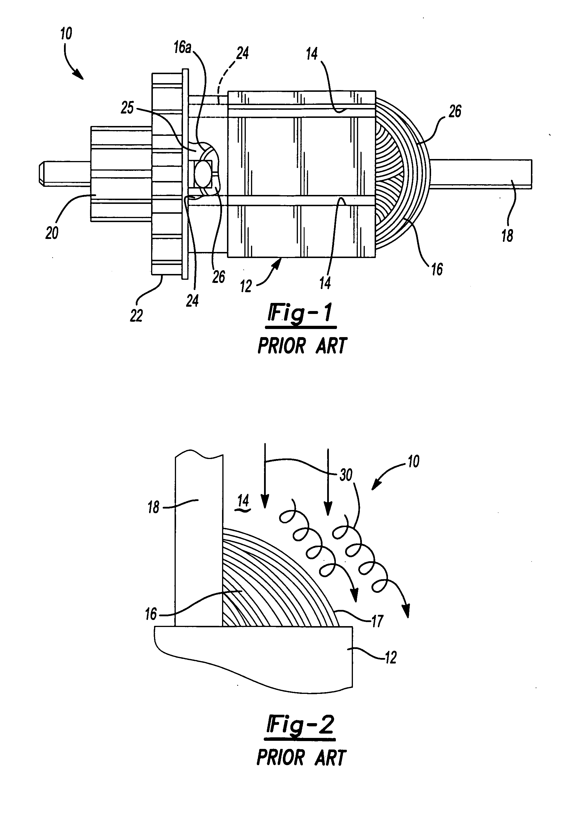
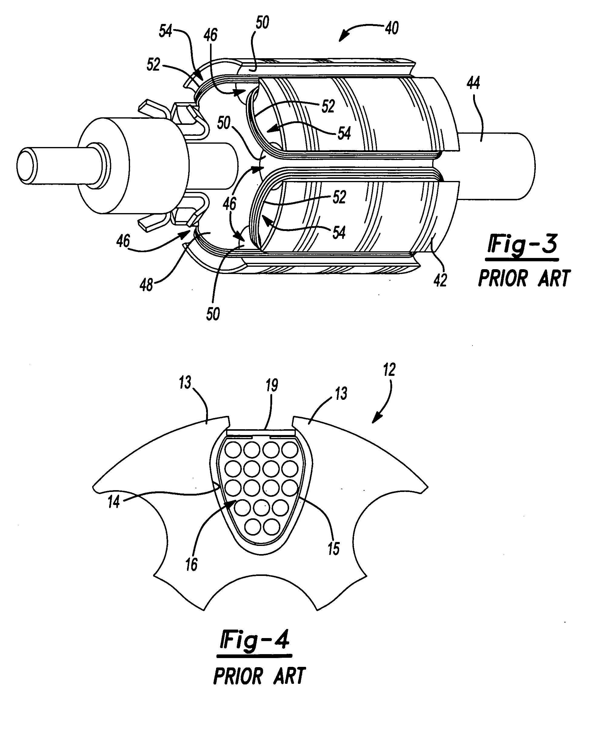
The technical problem addressed in this patent text is the wear and tear caused by abusive particles in the armature of electric motors and generators. The text describes various methods and drawbacks that have been used to protect the armature from these particles, but they often come with certain drawbacks such as increased manufacturing costs and difficulty in controlling the balancing process. The text also discusses the use of plastic insulators and coil stays to hold the magnet wires in place, but these methods have certain drawbacks such as poor thermal conductivity and non-homogeneity. The text also describes the use of double-insulated tools and the need for protective insulation to improve power tool performance.

Method used


Image

  • Electric motor and method of making same and method of making a power tool
  • Electric motor and method of making same and method of making a power tool
  • Electric motor and method of making same and method of making a power tool

Examples


Embodiment Construction

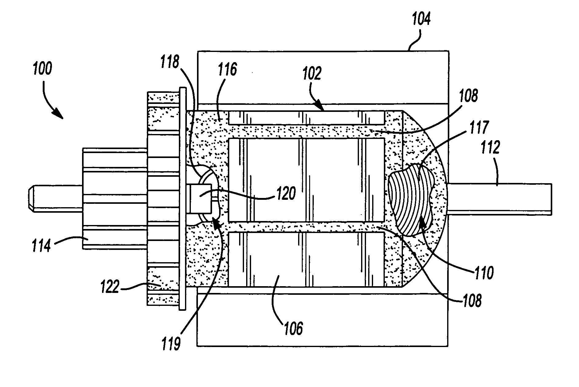
[0079] Referring now to FIG. 5, a motor 100 in accordance with a preferred embodiment of the present invention is disclosed. The motor 100 includes an armature 102 and a stator 104, the stator being illustrated in highly simplified fashion. The armature 102 incorporates a lamination stack 106 having a plurality of longitudinal slots 108 arranged circumferentially therearound. A plurality of magnet wires 110 are wound in the slots 108 to form a plurality of coil windings having end coils 117. An armature shaft 112 extends coaxially through the lamination stack 106 and has disposed on one end thereof a commutator 114. A thermally conductive plastic 116 is injection molded over the armature 102 so that the plastic flows into and through each of the slots 108. The thermally conductive plastic 116 is applied by placing the armature 102 in a suitable injection molding tool and then injecting the thermally conductive plastic 116 under a suitably high pressure into the molding tool. The the...


PUM

PropertyMeasurementUnit
Weightaaaaaaaaaa
Electrical conductoraaaaaaaaaa

Abstract

An electric motor has a stator in which an armature is disposed. The armature has a lamination stack having slots in which magnet wires are wound. An armature shaft extends coaxially through the lamination stack and a commutator is disposed on the armature shaft to which ends of the magnet wires are electrically coupled. The magnet wires are at least partially encased in thermally conductive plastic. When the thermally conductive plastic is molded, a balancing feature is formed of the thermally conductive plastic. In aspects, the balancing feature can include a layer of the plastic from which plastic can be removed during balancing; one or more balancing rings adjacent axial sides of the lamination stack from which plastic can be removed to balance the armature; or one or more balancing rings having one or more pockets therein in which one or more weights are disposed to balance the armature.

Description


Claims


Application Information

Patent Timeline
Owner BLACK & DECKER INC
Why Eureka
Try Eureka