Eureka AIR delivers breakthrough ideas for toughest innovation challenges, trusted by R&D personnel around the world.

Projector

a projector and projector body technology, applied in the field of projectors, can solve the problems of poor usability of operators, difficult to carry out zoom adjustment and focus adjustment, and poor operation efficiency of operators, and achieve the effects of improving operation efficiency, improving usability, and improving usability

Inactive Publication Date: 2006-11-16
FUNAI ELECTRIC CO LTD
View PDF4 Cites 15 Cited by
  • Summary
  • Abstract
  • Description
  • Claims
  • Application Information

AI Technical Summary

Benefits of technology

[0009] The present invention has been made in view of the circumstances and problems described above, and it is an object of the invention to provide a projector that easily allows eliminating such a situation that fingers of the hand can be projected onto a screen when carrying out a zoom adjustment and a focus adjustment through rotating manual operations, simplifying design in the vicinity of an attachment point of the lens barrel to the chassis, and making it easy to modify appearance design of said projector to a novel one.
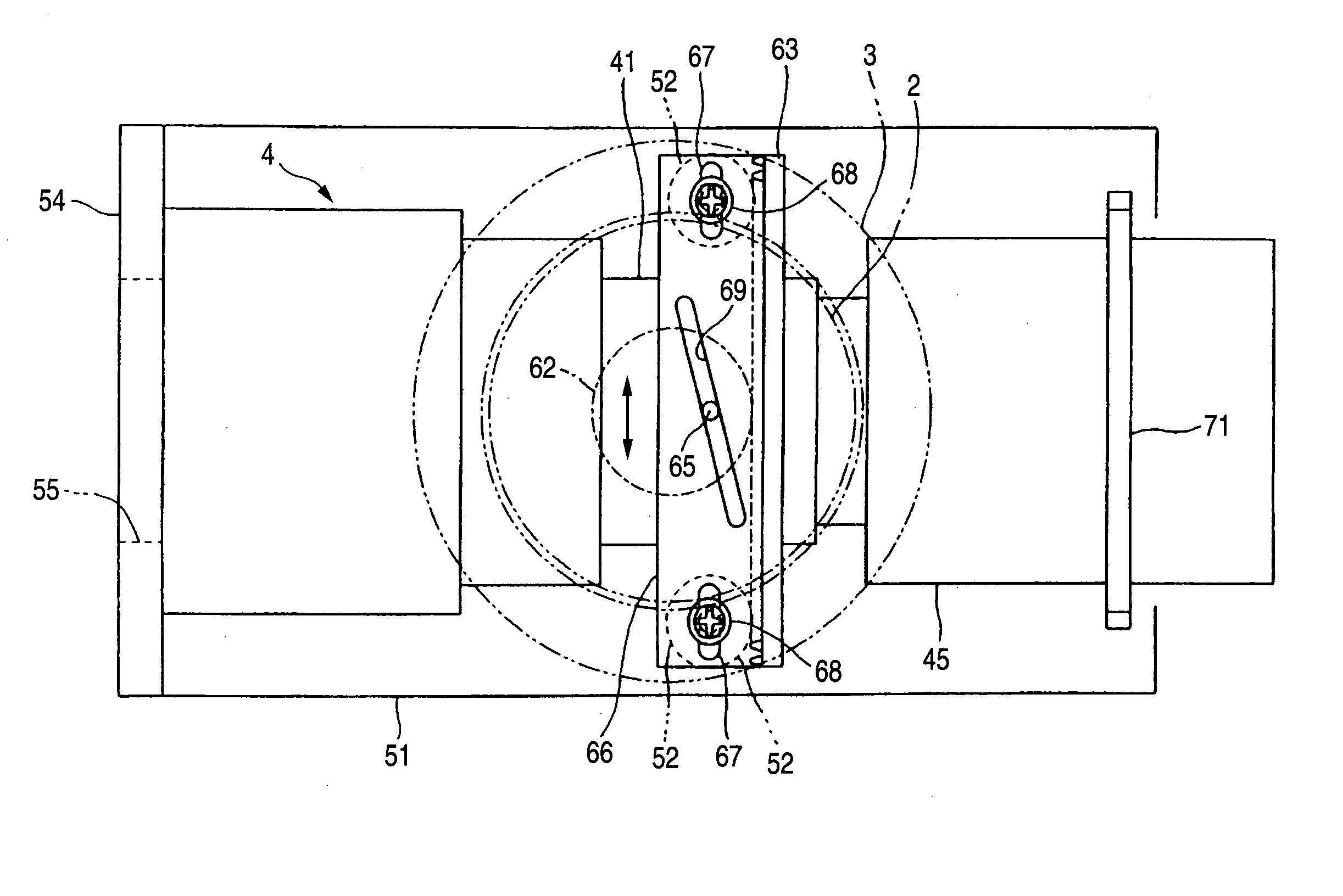
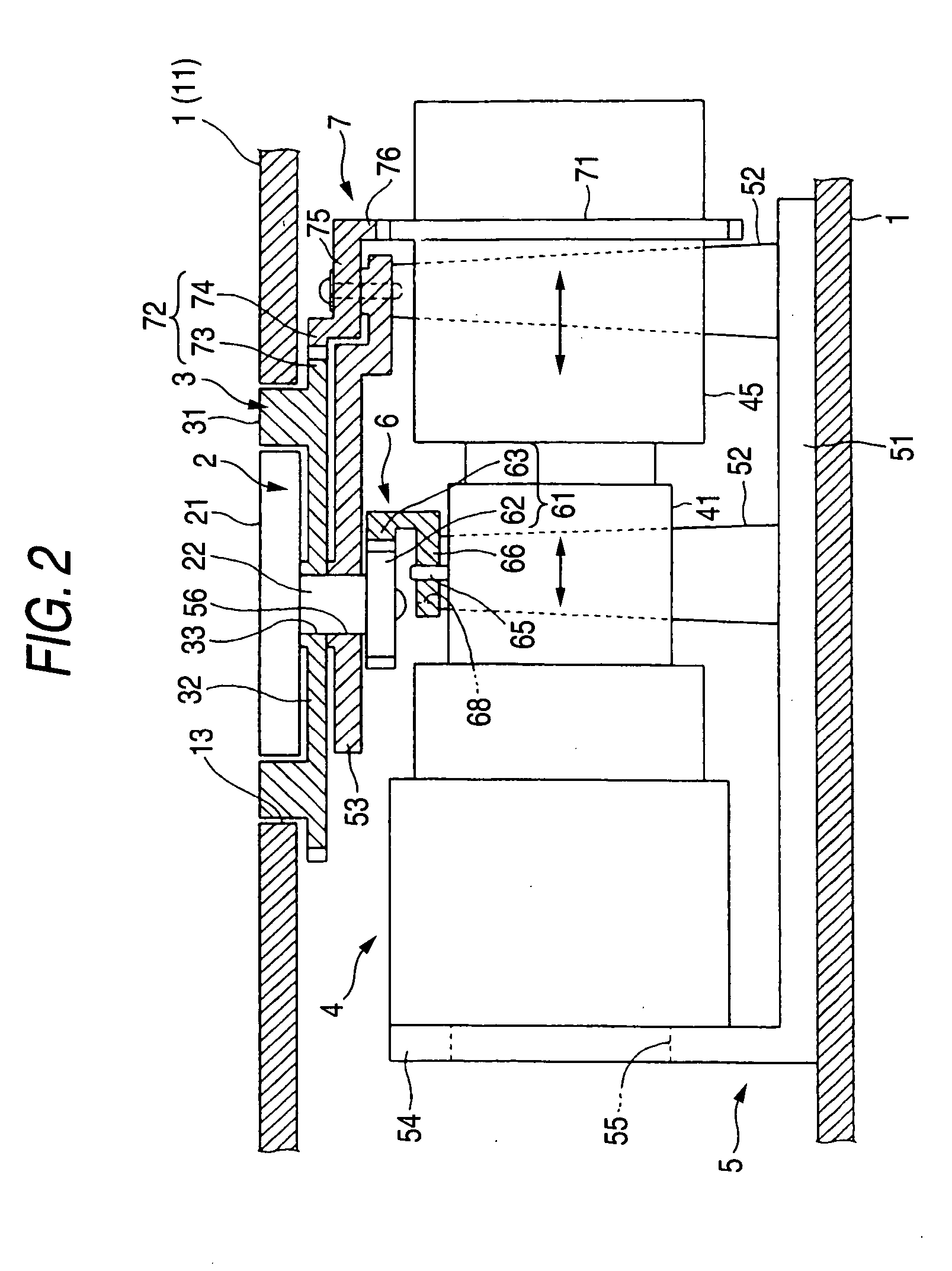
[0018] Since the zoom adjusting knob and focus adjusting knob are displaced at a point distant from the attachment point of the lens barrel, for example, at one point of the upper surface of the chassis, there is no room for such a situation that fingers of the hand are projected onto a screen when carrying out a zoom adjustment and a focus adjustment through rotating manual operations, so that operationality for an operator is greatly improved. Moreover, since the fact that the above-described respective knobs are disposed in the opening of the chassis at a point distant from the lens barrel is useful for making it easier to simplify design in the vicinity of the attachment point of the lens barrel to the chassis, making appearance design of said projector innovative and furthermore, modifying appearance design of said projector to an unconventional novel one, there is an advantage for the operator such that it becomes possible to use a projector excellent in operationality and moreover in an innovative design different from that of the conventional projector. In addition, although the zoom adjusting knob and focus adjusting knob are provided at a point different from that of the conventional projector, since rotations of those knobs owing to rotating manual operations are accurately transmitted to the zoom adjusting member and focus adjusting member via the pinion-rack mechanism, slide cam, movable body, and the like, it becomes possible to accurately carry out a zoom adjustment and a focus adjustment. Furthermore, it becomes possible to improve operationality when carrying out a rotating operation by pressing the operating surfaces of the zoom adjusting knob and focus adjusting knob with fingers without sacrificing a fitting space of other components or adversely affecting appearance design of said projector.

Problems solved by technology

However, in the projector disposed with a zoom adjusting ring and a focus adjusting ring around a lens barrel, when carrying out manual rotating operations by grasping these rings with fingers of the hand, it is often the case that operator's finger protrude in front of the projection lens and the fingers are projected onto the screen, and in that case, it becomes difficult to carry out a zoom adjustment and a focus adjustment.
Therefore, since it is necessary for an operator (user) to carry out a zoom adjustment and a focus adjustment while paying attention so as not to protrude his / her fingers of the hand in front of the projection lens, there has been concern that usability for the operator is inferior.
Moreover, in some cases, simplification of design in the vicinity of an attachment point of the lens barrel to the chassis is spoiled by the zoom adjustment ring and focus adjustment ring disposed therein, or it is pointed out that the zoom adjustment ring and focus adjustment ring become an obstacle when modification of appearance design of the projector to an innovative and novel one is intended.
Therefore, there is a problem such that it is difficult to carry out an operation to rotate the operating surfaces by pressing fingers thereagainst.
On the other hand, in order to protrude the operating surfaces as much as possible from the upper surface of the chassis to improve operationality thereof, since it becomes indispensable to increase the size (diameter) of the zoom ring and focus ring, a problem arises such that a fitting space of other components is sacrificed, and the width of protrusion of the rings from the upper surface of the chassis becomes too large in design.

Method used


Image

  • Projector
  • Projector
  • Projector

Examples


Embodiment Construction

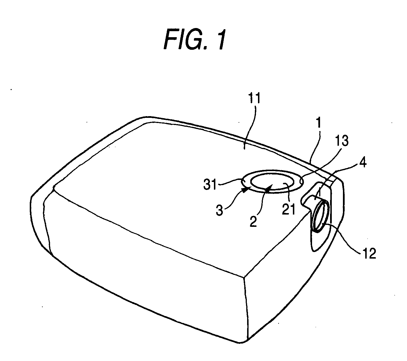
[0023]FIG. 1 is a schematic external perspective view of a projector according to an embodiment. As can be analogized from FIG. 1, in the projector of the embodiment, a chassis 1 thereof is divided into a bottom case, a top case, a front case, and the like united by fitting to each other, a projecting port 12 or the like is provided at a front face of the chassis 1, and a zoom adjusting knob 2 formed of a disk-like first member and a focus adjusting knob 3 formed of a circular ring-like second member are disposed in a circular opening 13 provided at a point of an upper plate portion 11 of the chassis 1, and the circular ring-like focus adjusting knob 3 is concentrically disposed at the outer side of the disk-like zoom adjusting knob 2. In addition, the whole of operating surfaces 21 and 31 of these respective knobs 2 and 3 is in a form not protruded from the upper surface of the chassis 1 so much, that is, positioned flush or almost flush with the upper surface of the chassis 1 and ...


PUM


Abstract

In a circular opening of an upper surface of a chassis, a disk-like zoom adjusting knob and a circular ring-like focus adjusting knob are disposed so as to be rotatable. A zoom interlocking mechanism includes a pinion-rack mechanism and a slide cam. A focus interlocking mechanism includes a pinion-rack mechanism and a slider. The zoom adjusting knob, zoom interlocking mechanism, and zoom adjusting member and the focus adjusting knob, focus interlocking mechanism, and focus adjusting member are fitted to a common body structure to construct a projecting optical unit.

Description

BACKGROUND [0001] 1. Technical Field [0002] The present application relates to a projector, particularly, a projector structured so that a zoom adjustment and a focus adjustment are carried out through manual operations. [0003] 2. Description of Related Art [0004] A projector projects an image onto a screen. The projector includes a zoom adjusting function and a focus adjusting function so as to correct quality and size of a projected image. Respective functions are exerted by correcting lens position through advancing and retracting operations of both zoom adjusting member and focus adjusting member. According to the projector, a zoom adjustment and a focus adjustment have been carried out by a rotating operation of a zoom adjusting ring and a focus adjusting ring disposed around a lens barrel housing a plurality of lenses by grasping the same with fingers of the hand. [0005] Meanwhile, a projector system in which a projection lens and a taking lens are arranged at the front face o...

Claims


Application Information

Patent Timeline
Patent Type & Authority Applications(United States)
IPC IPC(8): G03B3/00
CPCG03B3/00
Inventor HAMADA, SHINGO
Owner FUNAI ELECTRIC CO LTD
Why Eureka
Eureka Blog
Learn More