Systems and methods for a high capture angle, multiple angle light scattering (MALS) instrument

a technology of capture angle and light scattering, applied in the field of systems and methods for high capture angle, multiple angle light scattering (mals) instruments, can solve the problems of giardia forming oocysts or cysts, affecting the detection accuracy of microbial contaminants, and not being able to detect microbial contaminants in real-time and on-line to provide a warning

Inactive Publication Date: 2006-11-16
JMAR LLC A DELAWARE LLC
View PDF42 Cites 14 Cited by
  • Summary
  • Abstract
  • Description
  • Claims
  • Application Information

AI Technical Summary

Benefits of technology

[0012] A particle detection system uses a reflective optic comprising a curved surface to detect high angle scattered light generated by a particle in a liquid medium, when a laser beam is incident on the particle. When the particles transit the laser beam, light is scattered in all directions and is described by MIE scattering theory for particles about the size of the wavelength of light and larger or Rayleigh Scattering when the particles are smaller than the wavelength of light. By using the reflective optic, the scattered light can be detected over angles that are greater than normally obtainable. For example, the scattered light can be measured through an angle 90°.

Problems solved by technology

There are not only a number of chlorine resistant pathogens such as Cryptosporidium that can contaminate drinking water systems, but also potentially harmful microorganisms that can be introduced, either accidentally or intentionally, and propagate under suitable environmental conditions.
Due to the length of time for standard laboratory methods to yield results, typically 24-72 hours, there has not been a reliable system to detect microbial contaminants in real-time and on line to provide a warning of pathogen contamination events.
Conventional microbiological methods can be used to detect some harmful microorganisms; however, such methods provide limit results.
Cryptosporidium and Giardia form oocysts or cysts and cannot be cultured in conventional ways.
Practically, such methods have, therefore, proved to be time consuming, costly, and of little effectiveness for many current environmental field applications.
Conventional MALS devices and methods often differ in the amount of time to obtain results, degree of specificity, sampling frequency, concentration sensitivity, operating complexity, and cost of ownership.

Method used


Image

  • Systems and methods for a high capture angle, multiple angle light scattering (MALS) instrument
  • Systems and methods for a high capture angle, multiple angle light scattering (MALS) instrument
  • Systems and methods for a high capture angle, multiple angle light scattering (MALS) instrument

Examples


Embodiment Construction

.”

BRIEF DESCRIPTION OF THE DRAWINGS

[0014] Features, aspects, and embodiments of the inventions are described in conjunction with the attached drawings, in which:

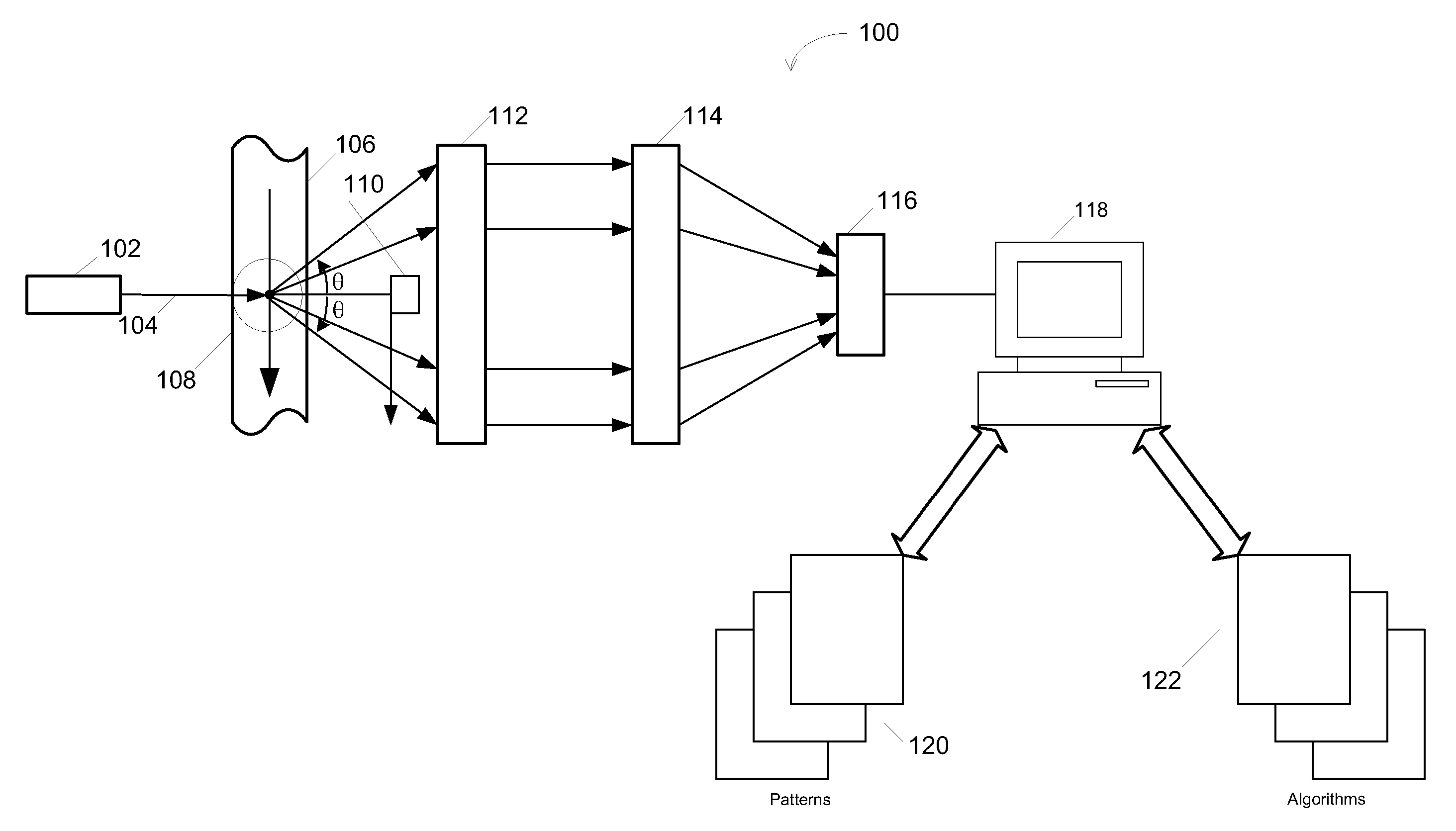
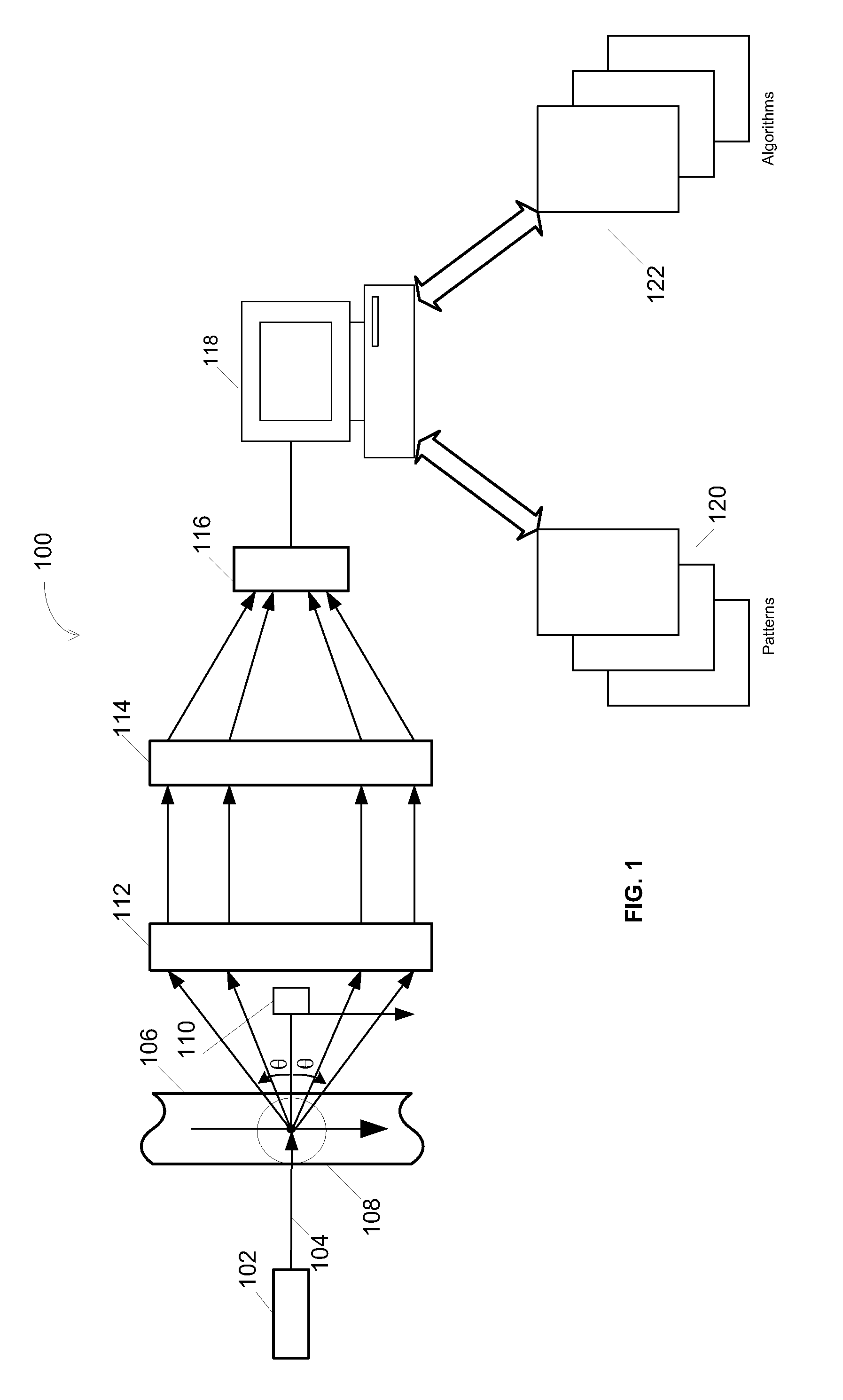
[0015]FIG. 1 is a diagram illustrating an example embodiment of a particle detection system;

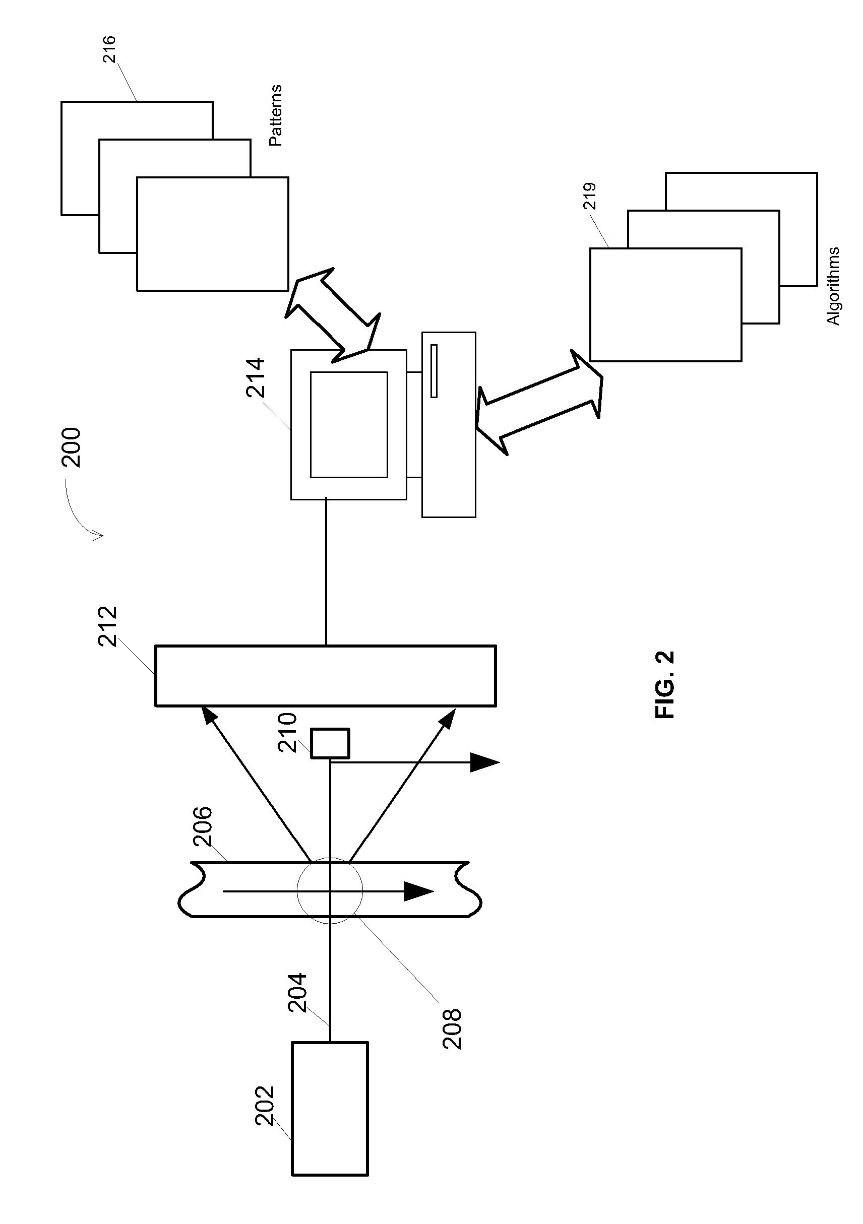
[0016]FIG. 2 is a diagram illustrating another example embodiment of a particle detection system;

[0017]FIG. 3A is a picture of B. suptilis spores;

[0018]FIGS. 3B and 3C are pictures illustrating example optical signatures that can be generated by the systems of FIGS. 1 and 2 for the B. suptilis spores of FIG. 3A;

[0019]FIG. 4A is a picture of a ball of plastic spheres;

[0020]FIGS. 4B and 4C are pictures illustrating example optical signatures that can be generated by the systems of FIGS. 1 and 2 for the ball of plastic spheres of FIG. 4A;

[0021]FIGS. 5-7 are diagrams illustrating a technique for using illumination incident at an angle in a light scattering detection system, such as the systems of FIGS. 1 and 2;

[0022]FIG. 8 is a d...


PUM

PropertyMeasurementUnit
angleaaaaaaaaaa
sizeaaaaaaaaaa
diameteraaaaaaaaaa

Abstract

A particle detection system uses a reflective optic comprising a curved surface to detect high angle scattered light generated by a particle in a liquid medium, when a laser beam is incident on the particle. When the particles transit the laser beam, light is scattered in all directions and is described by MIE scattering theory for particles about the size of the wavelength of light and larger or Rayleigh Scattering when the particles are smaller than the wavelength of light. By using the reflective optic, the scattered light can be detected over angles that are greater than normally obtainable.

Description

FIELD OF THE INVENTION [0001] This application claims the priority under 35 U.S.C. 119(e) to U.S. Provisional Application 60 / 676,730, entitled “High Capture Angle MALS Instrument For Liquid Suspensions of Microrganisms,” filed May 2, 2005. This Application also claims priority as a Continuation-In-Part under 35 U.S.C. 120 to U.S. patent application Ser. No. 11 / 231,350, entitled “Systems and Methods for Detecting Scattered Light From a Particle Using Illumination Incident at an Angle,” filed Sep. 19, 2005. Both of the above applications are incorporated herein in the entirety as if set forth in full.BACKGROUND [0002] 1. Field of the Invention [0003] Embodiments of the invention relate to identifying particles, and in particular to identifying particles in a liquid using illumination incident at an angle. [0004] 2. Background of the Invention [0005] A major concern for, e.g., water utilities is the detection and control of pathogenic microorganisms, both known and emerging, in potable...

Claims


Application Information

Patent Timeline
Patent Type & Authority Applications(United States)
IPC IPC(8): G01N15/02
CPCG01N15/147G01N2015/0088G01N15/1475
Inventor BLOOM, SCOTT H.CHAN, VICTOR J.CASHION, STEVEN A.
Owner JMAR LLC A DELAWARE LLC
Why Eureka
Try Eureka