
Circuit with at least one catalytic measuring element

a technology of catalytic measuring element and circuit, applied in chemical analysis using catalysis, chemical analysis using combustion, chemical methods analysis, etc., can solve the problems of increasing the weight of such devices in a disadvantageous manner, consuming electric power, and a considerable drawback, and achieves an especially low energy consumption

Active Publication Date: 2006-11-16
DRAGER SAFETY
View PDF0 Cites 16 Cited by
  • Summary
  • Abstract
  • Description
  • Claims
  • Application Information

AI Technical Summary

Benefits of technology

[0007] The object of the present invention is to provide a circuit with catalytic measuring elements, which can be operated with an especially low energy consumption.
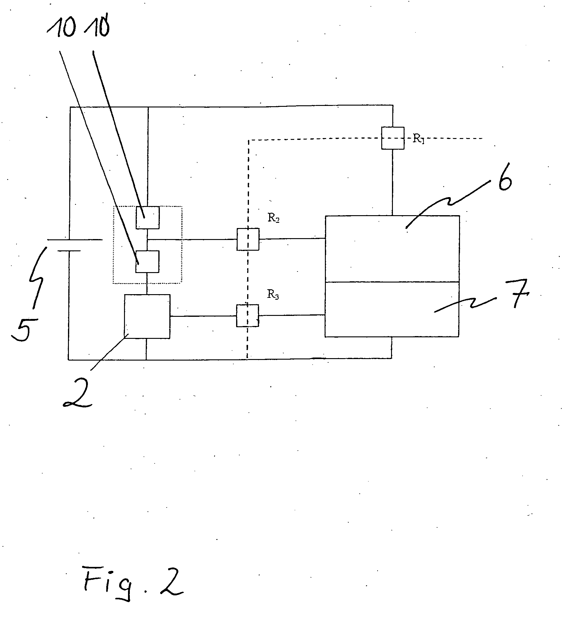
[0010] It is thus possible according to the present invention to do away with a protective resistor or a thermal safety device arranged upstream. The present invention can be advantageously used in circuits that contain a plurality of, but at least two catalytic measuring elements. In particular, circuits that contain at least one pellistor can be set up in the manner according to the present invention. At least one pellistor is advantageously dimensioned here such that it limits the current at a point in time to a value that prevents ignition by a spark in an environment with explosion hazard. This function is ensured according to the present invention regardless of the operating temperature at which the pellistor is used for measurements.

Problems solved by technology

Also, they are possibly used in the presence of an explosion hazard.
The drawback of such a circuit is, however, that both a protective resistor and a thermal safety device represent separate users and they consume electric power.
This represents a considerable drawback, especially in case of portable devices that are battery-operated.
The energy storage means necessary for this, for example, batteries, increase the weight of such devices in a disadvantageous manner.

Method used


Image

  • Circuit with at least one catalytic measuring element
  • Circuit with at least one catalytic measuring element
  • Circuit with at least one catalytic measuring element

Examples


Embodiment Construction

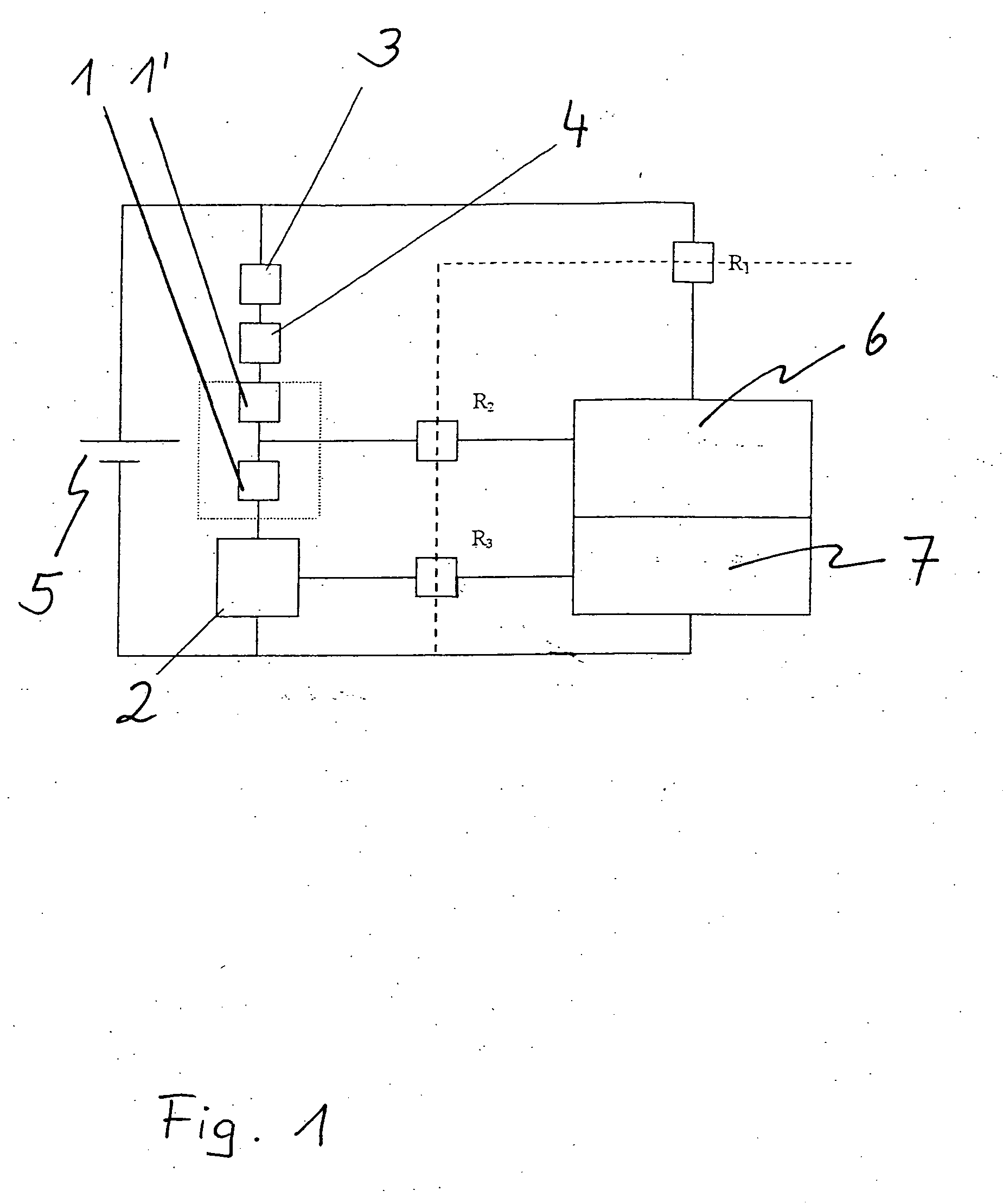
[0018] Referring to the drawings in particular, FIG. 1 shows a circuit with two pellistors as catalytic measuring elements 1, 1′. These are connected in series with a power electronic assembly unit 2, a protective resistor 3 and a thermal safety device 4 as a protection for the protective resistor 3 and all series-connected elements. The output voltage of a power source 5 is applied to this series-connected arrangement. An electronic assembly unit with an evaluating electronic unit 6 is used to evaluate the measured signals, which are sent by the arrangement of pellistors. An assembly unit with actuating electronic unit 7 is used to actuate the power electronic assembly unit 2. The evaluating electronic unit and the actuating electronic unit are likewise supplied by the power source 5, but are connected to the power source 5, the output signal of the pellistors and the power electronic assembly unit 2 via high-ohmic resistors R1, R2, R3.

[0019]FIG. 2 shows a circuit designed accordi...


PUM


Abstract

A circuit with at least one catalytic measuring element (1), in which the at least one catalytic measuring element (1) is connected to a supply voltage (5) without a protective resistor and without a thermal safety device arranged upstream. The circuit makes it possible to develop gas-measuring devices with catalytic measuring elements that are characterized by an especially low power consumption.

Description

CROSS REFERENCE TO RELATED APPLICATIONS [0001] This application claims the benefit of priority under 35 U.S.C. §119 of German Patent Application DE 10 2005 022 471.7 filed May 14, 2005, the entire contents of which are incorporated herein by reference. FIELD OF THE INVENTION [0002] The present invention pertains to a circuit with at least one catalytic measuring element. BACKGROUND OF THE INVENTION [0003] Devices that operate with catalytic measuring elements to perform gas measurements have been used in gas measuring engineering applications. In particular, pellistors are widely used for in gas measuring engineering applications. [0004] General conditions must be taken into account when such measuring elements are used. These conditions arise from the fact that the electric properties of such catalytic measuring elements may change during the measurement. Also, they are possibly used in the presence of an explosion hazard. [0005] The pellistors are considered to be semiconductor el...

Claims


Application Information

Patent Timeline
IPC IPC(8): G01N31/10
CPCG01N27/16
Inventor MARTENS, MATTHIASSCHLICHTE, MLADEN
Owner DRAGER SAFETY
Learn More