Contact terminal structure

a technology of contact terminals and terminals, which is applied in the field of contact terminals, can solve the problems of not giving a correct electrical fluctuation, and not resulting in a correct contact between the base and the motherboard of an integrated circuit, and achieves the effect of easy bonding

Inactive Publication Date: 2006-11-16
WONTEN TECH
View PDF2 Cites 17 Cited by
  • Summary
  • Abstract
  • Description
  • Claims
  • Application Information

AI Technical Summary

Benefits of technology

[0009] A main objective of the invention is to solve and / or avoid above-described disadvantages associated with the prior art, and make possible bonding more easily and precisely for the solder ball with the soldering portion on the contact terminal.

Problems solved by technology

Consequently, this structure could not give a correct electrical contact between the base and the motherboard of an integrated circuit, too.
However, there are several disadvantages associated with this kind of contact terminal because the bonding between the contact terminal and the solder ball is relatively uneasy to be done and a fluctuation tends to be caused between adjacent solder balls and the solder ball tends to drop off during its placing.
Furthermore, no aligning structure exists between the contact terminal and the base such that after mounting the contact terminal into the terminal block on the base, a fluctuation could be caused.
Consequently, in view of the foregoing, it is evident that this prior art structure could not result in a correct contact between the base and the motherboard of an integrated circuit.

Method used


Image

  • Contact terminal structure
  • Contact terminal structure
  • Contact terminal structure

Examples


Embodiment Construction

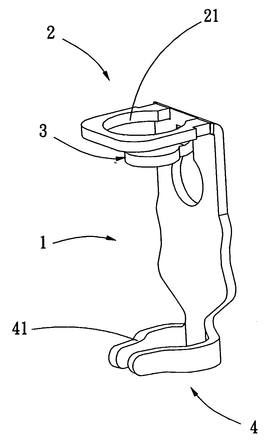
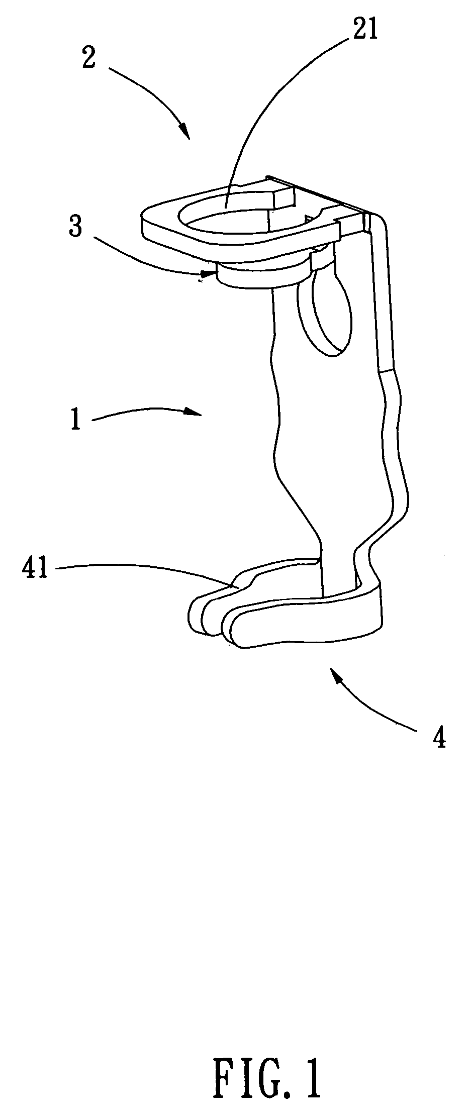
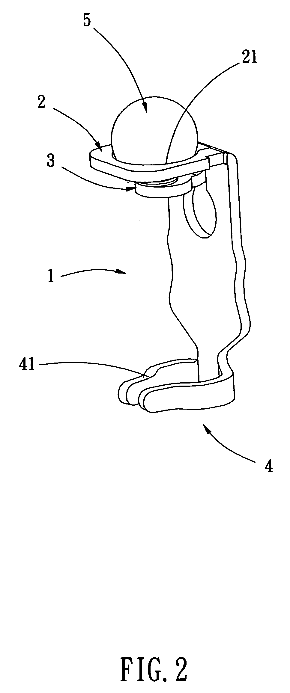
[0015] Referring to FIGS. 1 and 2, showing schematically the perspective view and the practice of an embodiment of a contact terminal structure according to the invention, respectively, said contact terminal structure comprises:

[0016] a main body 1; and

[0017] a soldering end 2, extending vertically from one end of said main body 1 and providing with an aligning portion 21 of an arcuate hollow shape for placing a solder ball 5, wherein the periphery of said aligning portion 21 may be in a rounded concave form; and

[0018] a supporting portion 3, formed from said main body 1 by a stamping process, whereby, as said solder ball 5 is placed in said aligning portion 21, said solder ball 5 will be stopped at said supporting portion 3 in a manner such that the placing depth of said solder ball 5 can be controlled, wherein said supporting portion 3 is provided adjacent to the inner side of said soldering portion 2; and

[0019] a contact end 4, extending from another end of said main body 1 a...


PUM


Abstract

An improvement on a contact terminal structure to be disposed into the terminal block on the base of an integrated circuit, comprises a main body, a soldering end extending vertically from one end of said main body and providing with an aligning portion of an arcuate hollow shape for placing a solder ball, a supporting portion extending vertically from said main body and being used for supporting said solder ball, and a contact end extending vertically from another end of said main body and providing contortedly with a corresponding contact portion at an appropriate position thereon. This structure can allow said solder ball bond more precisely with said soldering portion on said contact terminal.

Description

BACKGROUND OF THE INVENTION [0001] 1. Field of the Invention [0002] The invention relates to an improvement on a contact terminal structure, more particularly to a structure for solving the problem of the bonding and alignment between a solder ball and a contact terminal such that the solder ball can be more easily and precisely bonded with the contact terminal. [0003] 2. Description of the Prior Art [0004] It is known, in the past, the contact bonding between a base and a motherboard in an integrated circuit was in a manner of mounting before soldering. But at present, the contact bonding is gradually adopting a manner of placing a solder ball on a contact terminal in an integrated circuit base first, and then soldering the integrated circuit base on a motherboard directly by means of a soldering process. [0005] A structure as disclosed in U.S. Pat. No. 6,267,615 comprising a contact terminal consisted essentially of a base part, a wing part, a flexible arm, a holding part and a su...

Claims


Application Information

Patent Timeline
Patent Type & Authority Applications(United States)
IPC IPC(8): H05K1/00
CPCH05K3/3426H05K2201/10189H05K2203/0485H05K2203/041H05K2201/10984Y02P70/50
Inventor CHEN, WAN-TIEN
Owner WONTEN TECH
Why Eureka
Try Eureka