Structural unit in the form of a cavity-formed part, and use thereof

Inactive Publication Date: 2006-11-16
SKS SITZKOMPONENTEN
View PDF3 Cites 11 Cited by
  • Summary
  • Abstract
  • Description
  • Claims
  • Application Information

AI Technical Summary

Benefits of technology

[0011] As can the first formed part, so can also the second formed part have a multilayered structure having a preferably thermoplastic support layer and a flat, in particular textile, material associated to the support layer, the flat material of the second formed part likewise being laminated to the support layer on the side of the support layer facing away from the cavity, so that a uniform surface quality or structure can be realized for the entire inventive structural unit.
[0012] As further extensively described hereinafter, the formed parts forming the inventive structural unit are not limited to an above-described two-layer structure. Rather, it is equally possible that a support is additionally provided, the optional support being bonded to the support layer, preferably on the side facing the cavity, so that to some extent a “sandwich structure” results, in which the support layer so to speak forms the core layer of the layered or composite material. As a result, particularly dimensionally stable structures or shapes can be achieved, which can also withstand a high force load. As a result of a targeted combination, for example, of a two-layered formed part with a deformable support layer and a three-layered formed part with a solid support, the abovementioned properties, purpose-matched formability and high load-bearing capacity, can be combined with one another.
[0013] An underlying concept of the present invention is to be considered to be, in particular, that as starting materials for the inventive structural unit, use is made of pre-fabricated multilayer sheet-type material parts containing all components or

Problems solved by technology

Since in the prior art it is only envisaged, as mentioned above, to process single-layer thermoplastic materials in this manner, it is not possible, for example, to produce products having particular properties, such as special surface properties.
Such single-layer cavity formed parts are thus not suitable for use, e.g., in furniture, in which, in addition to a certain structural strength, precisely also special surface properties (e.g. optical or haptic properties) and anatomical or ergonomic properties (seating comfort in the case of seating furniture) play an important part.
A disadvantage in this case, however, is that the flat material is only applied after the forming, because this makes the adhesion difficult, and that the high number of process steps is more labor intensive and costly.
In particular, it is frequently impossible to bond flat textile material over the surface to the formed material since, in particular in the region of large deformations (e.g. in the case of large bends, indentations or projections and the like), large strain or compression of the flat textile material occurs, which can frequently lead to detachment or delamination of the flat material.
In addition, with respect to the subsequent application of a layer to the three-dimensional structure, frequently unwanted crease formation occurs.
A further disadvantage in this process is considered to be that owing to the subsequent fixing of the flat textile material to the three-dimensional structure, a non-uniform strain of the flat textile material can result, which leads to a non-uniform surface profile.
Finally, pores or non-uniform return forces resulting from the subsequent, occasional non-uniform, “stretching” of the flat textile material onto the support structure can lead to subsequent deformation of the formed part.
However, discontinuous bonding is also equally possible, for example by means of point-like or raster-like application of the adhesive.

Method used


Image

  • Structural unit in the form of a cavity-formed part, and use thereof
  • Structural unit in the form of a cavity-formed part, and use thereof

Examples


Embodiment Construction

[0032] For the purposes of promoting an understanding of the principles of the invention, reference will now be made to the embodiments illustrated in the drawings and specific language will be used to describe the same. It will nevertheless be understood that no limitation of the scope of the invention is thereby intended, such alterations and further modifications in the illustrated device, and such further applications of the principles of the invention as illustrated therein being contemplated as would normally occur to one skilled in the art to which the invention relates.

[0033] In the figures the same reference signs are used for identical or similar parts, corresponding properties and advantages being achieved, even when repeated description is omitted for the sake of simplification.

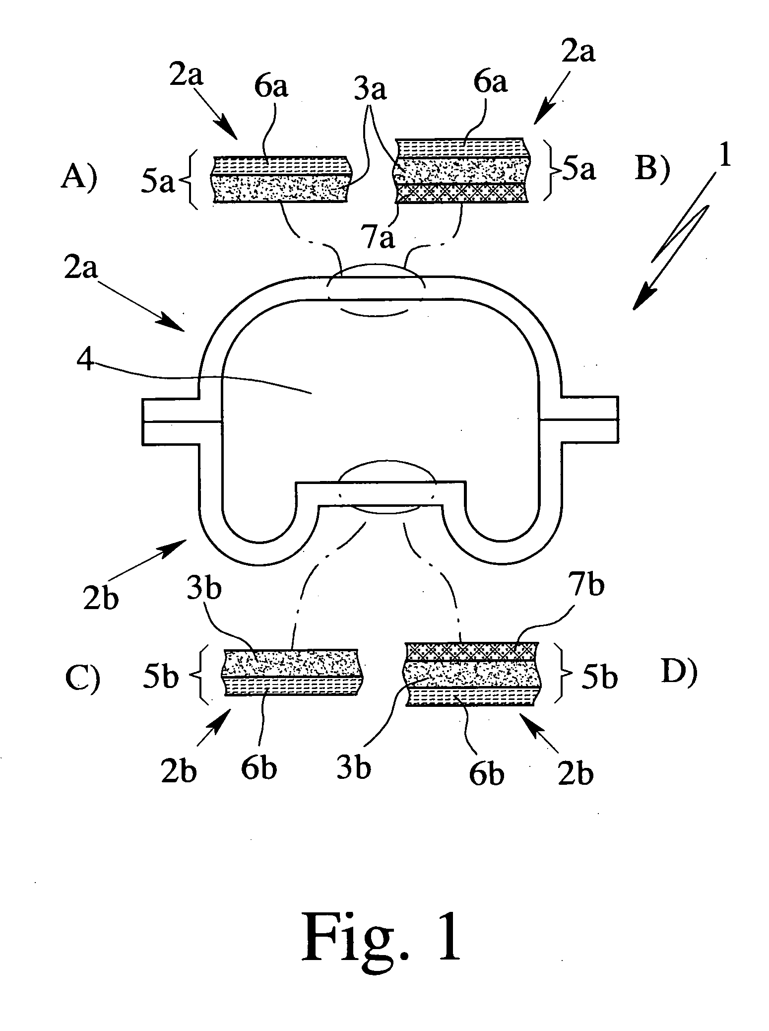
[0034]FIG. 1 shows an inventive structural unit 1 which comprises a first formed part 2a having a support layer 3a and a second formed part 2b having a support layer 3b. According to the inventi...


PUM

PropertyMeasurementUnit
Temperatureaaaaaaaaaa
Elongationaaaaaaaaaa
Temperatureaaaaaaaaaa

Abstract

The present invention relates to a structural unit (1) made of at least two formed parts (2a, 2b) which fashion or form at least one cavity (4), at least the first formed part (2a) having a multilayered structure (5a) having a flat, in particular textile, material (6a) associated to a support layer (3a), and the flat material (6a) being laminated to the support layer (3a) on the side of the support layer (3a) facing away from the cavity (4), and also to furnishing articles which have the structural unit (1), and to a process for production of the structural unit (1).

Description

CROSS REFERENCES TO RELATED APPLICATIONS [0001] The present application claims priority to German Patent Application Serial No. DE 20 2005 007 647.3, filed May 10, 2005; German Patent Application Serial No. DE 10 2005 054 063.5, filed Nov. 10, 2005; and German Patent Application Serial No. DE 10 2005 062 351.4, filed Dec. 23, 2005, all of which are hereby incorporated by reference in their entirety. BACKGROUND OF THE INVENTION [0002] The present invention relates to a structural unit in the form of a cavity-formed part and also to use thereof, in particular for production of furnishing articles, in particular furniture, preferably seating furniture, decorative elements, cavity channels and the like, and also the articles of the abovementioned type produced therewith as such. Finally, the present invention relates to a process for production of such a structural unit. [0003] Three-dimensional cavity-formed parts are known from the prior art which are produced from sheet-type starting...

Claims


Application Information

Patent Timeline
IPC IPC(8): B32B5/24B32B5/18
CPCA47C3/16B32B2509/00A47C7/24B29C44/06B29C44/1228B29C49/0047B29C51/02B29C51/10B29C51/145B29C51/267B29C66/1312B29C66/54B29C66/723B29C2791/001B29C2791/006B29K2313/02B29L2009/00B29L2022/02B29L2031/003B29L2031/44B29L2031/443B29L2031/771B32B1/02B32B3/28B32B5/00B32B5/02B32B5/18B32B5/245B32B27/12B32B27/30B32B27/32B32B2250/40B32B2266/025B32B2266/0278B32B2266/08B32B2274/00B32B2307/51B32B2307/546B32B2307/5825B32B2479/00A47C5/00Y10T442/3325B29C44/14B29C49/0691B32B1/00
Inventor SALZMANN, OLIVERFRANZKE, GUIDO
Owner SKS SITZKOMPONENTEN
Why Eureka
Try Eureka