Radio communication apparatus, transmitter apparatus, receiver apparatus and radio communication system

a radio communication and transmitter technology, applied in the field of radio communication equipment, can solve the problems of sudden deterioration of the signal-to-noise ratio (s/n), increased computation amount, and difficulty in increasing the number of transmission symbols, and achieves excellent communication quality and efficient communication

Inactive Publication Date: 2006-11-16
MITSUBISHI ELECTRIC CORP
View PDF9 Cites 29 Cited by
  • Summary
  • Abstract
  • Description
  • Claims
  • Application Information

AI Technical Summary

Benefits of technology

[0012] According to the present invention, an optimal MIMO channel structure (channel division by antennas, channel division by STC) is determined from various parameters such as the numbers of antennas provided at a transmitter and a receiver, computational capacity, and channel state. Efficient communication can thereby be carried out as compared with the conventional technique. Further, even in a communication environment in which an inverse matrix does not exist in a conventional SDM method, there is a high possibility that an equalization matrix can be generated by applying STC. Therefore, excellent communication quality, which is the feature of STC, can be realized while maintaining high-speed communication, which is the feature of SDM.

Problems solved by technology

However, in the conventional communication apparatus that employs the SDM method, since inverse matrix computation is needed for channel separation, the amount of computation increases.
Further, for example, when an inverse matrix does not exist in the inverse matrix computation (or the matrix Eq. is near 0), a sudden deterioration in the signal-to-noise ratio (S / N) arises.
In the conventional communication apparatus that employs the STC method, since the same signal is transmitted for plural times, it is difficult to increase the number of transmission symbols.
In other words, they have inherent problems.

Method used


Image

  • Radio communication apparatus, transmitter apparatus, receiver apparatus and radio communication system
  • Radio communication apparatus, transmitter apparatus, receiver apparatus and radio communication system
  • Radio communication apparatus, transmitter apparatus, receiver apparatus and radio communication system

Examples


first embodiment

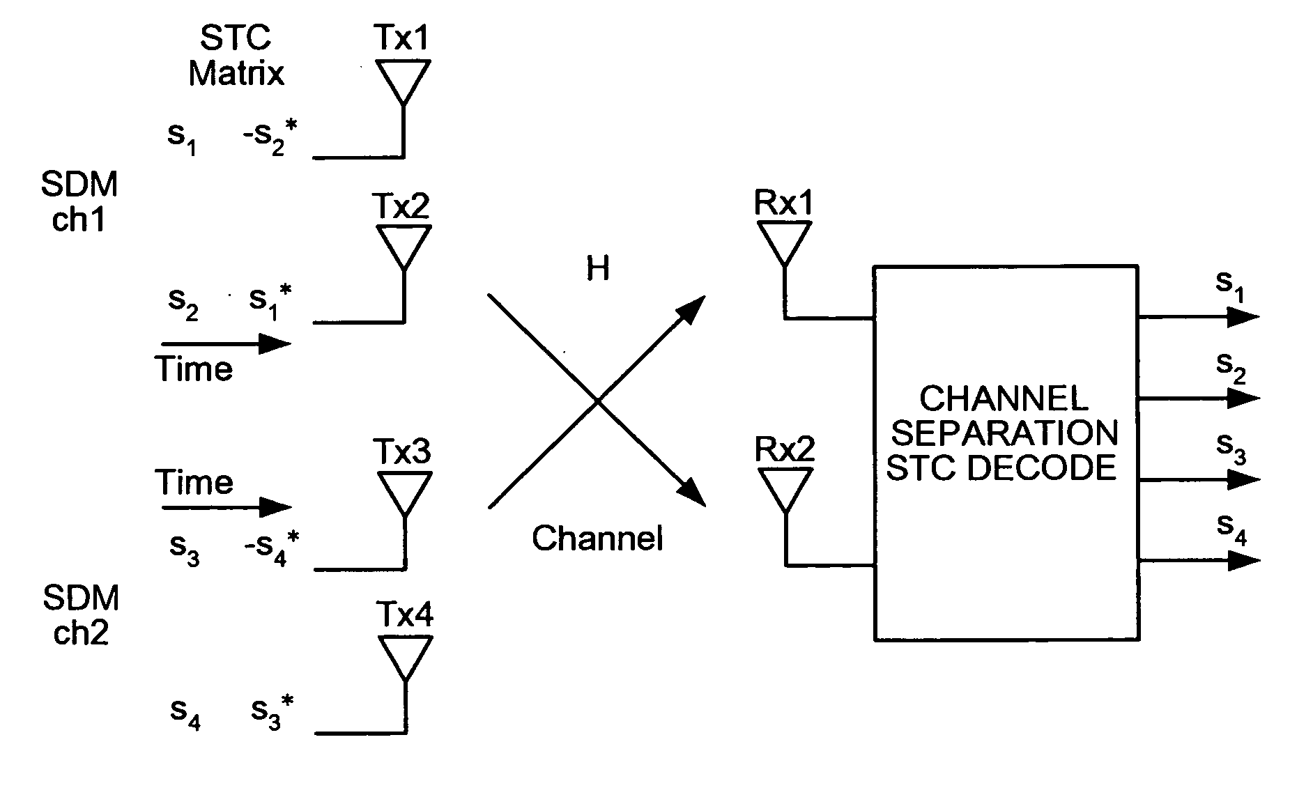
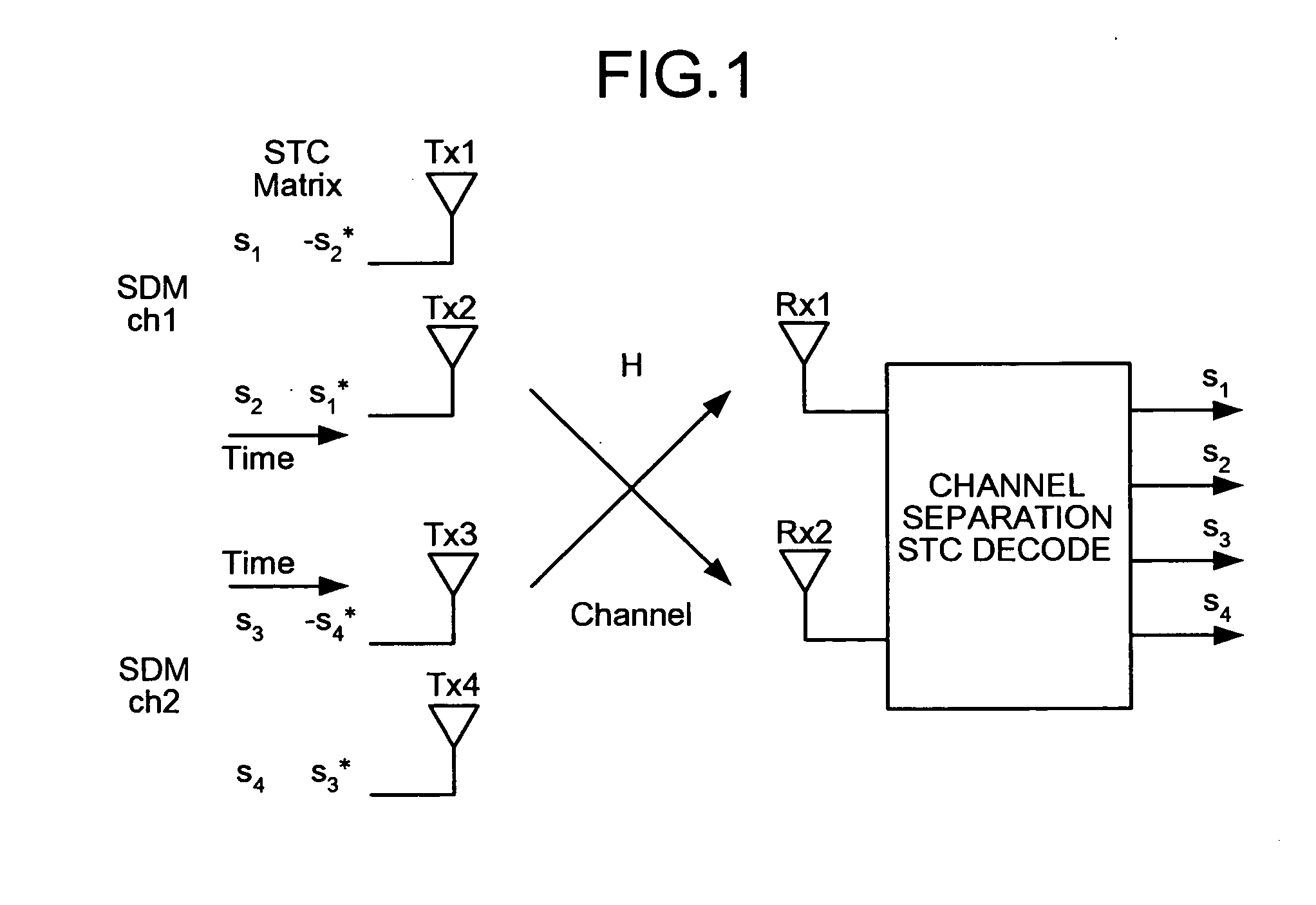
[0019] Processing executed by a radio communication apparatus according to the present invention will be explained theoretically. In the explanation, the number of subcarriers is 1.

[0020] Given that a channel gain from a transmission antenna i to a reception antenna k is expressed as hik, when there are two transmission antennas for example, an SDM method can be expressed by following Eq. (1). rj represents a reception signal at a reception antenna j, and xj represents a transmission signal at a transmission antenna j (equivalent to channel j). Noise is ignored herein. [r1r2]=[h11h21h12h22]⁡[x1x2](1)

[0021] When the STC method also uses a specific signal arrangement matrix, description similar to Eq. (1) is possible. For example, when a matrix of two transmission antennas and Rate=1 is used, given that a reception signal at time n is yn, it can be expressed as per following Eq. (2). [y1y2]=[h11h21h21*-h11*]⁡[x1x2](2)

[0022] The difference from the SDM method is that, since there is...

second embodiment

[0040]FIG. 4 is a configuration diagram of a receiver according to a second embodiment of the present invention. This receiver has a coherent-band width measuring unit 21a that measures a coherent band width of the channel, and a channel estimating unit 15a that carries out channel estimation by using coherent band width information S20 and a known pattern in the reception signal. Like reference signs designate like parts as those according to the first embodiment, and description thereof is omitted. Only operation that differs from the first embodiment is described herein.

[0041] The coherent-band width measuring unit 21a periodically observes the baseband signals S11, and computes a coherent band width at the current channel (a frequency width at which the channel is considered to be substantially constant). Usually for example, a pilot signal portion is used because a known signal is needed for this computation. Since it is considered to be a substantially constant channel within...

third embodiment

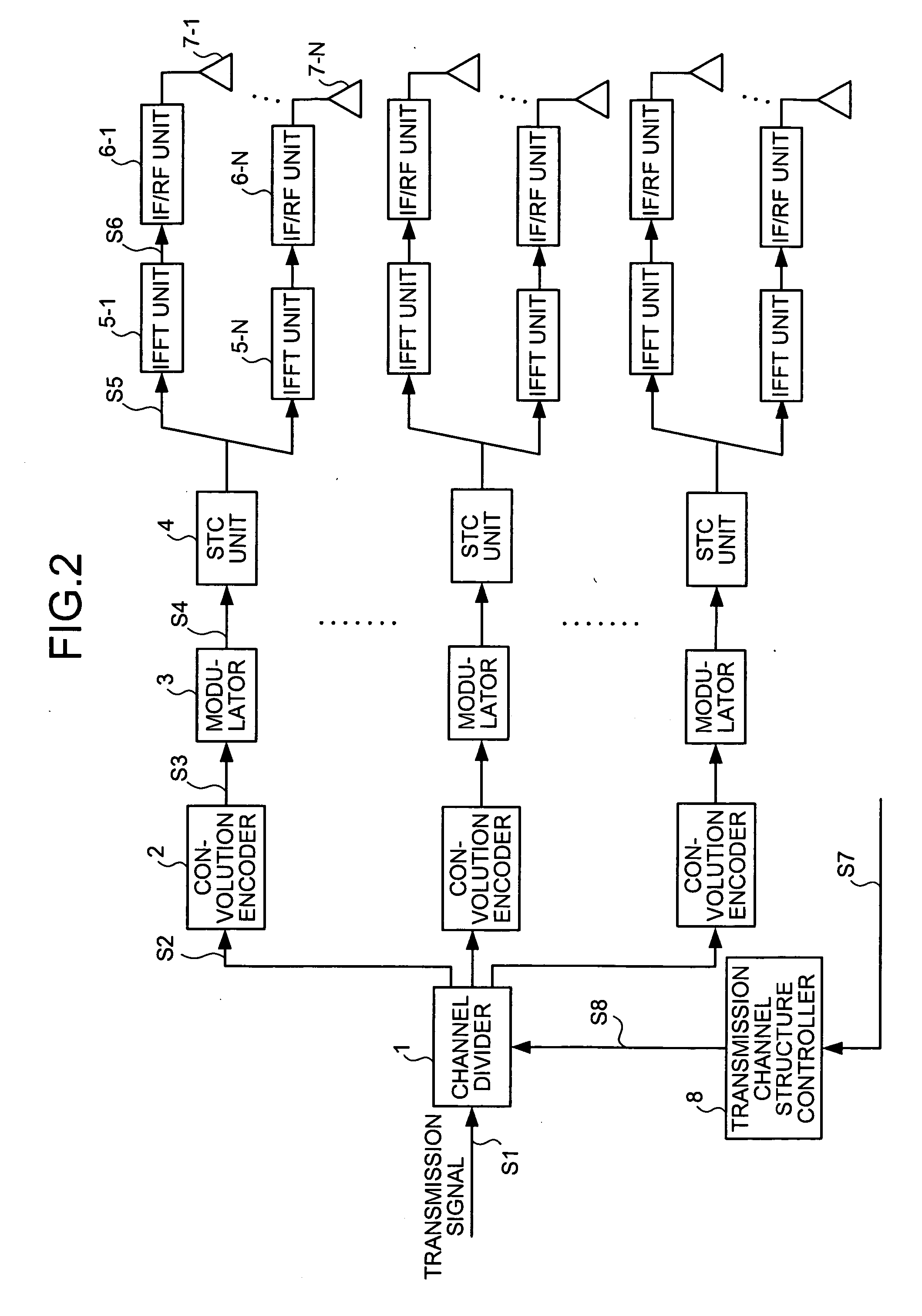
[0044]FIG. 5 is a configuration diagram of a transmitter according to a third embodiment of the present invention. This transmitter has beam forming units 9-1 through 9-M (an integer of 2 or more) that carry out complex multiplication in transmission antenna units on data of the respective transmission channels and control transmitting directions, and adding units 10-1 through 10-N that add all of the transmission signals after beam forming control corresponding to the respective transmission antennas. Like reference signs designate like parts as those according to the first embodiment, and description thereof is omitted. Only operation that differs from the first embodiment is described herein.

[0045] According to the first embodiment, the transmission signals S5 after STC processing are transmitted omnidirectionally from the respective transmission antennas. On the other hand, in the present embodiment, beam forming by plural antennas is applied to the transmission signals S5. In ...


PUM


Abstract

A channel dividing unit of a transmitter divides a transmission signal into a plurality of channels based on channel structure information indicating a method of structuring an MIMO informed from a receiver. An STC unit realizes transmission diversity according to STC processing for each of the channels divided. A channel estimating unit of the receiver estimates a channel gain for transmission and reception of a signal. Based on a result of estimation of the channel gain, a physical configuration of the transmitter, and a physical configuration of the receiver, a transmission-side channel-structure determining unit of the receiver determines a structure of an MIMO channel, and informs channel structure information to the transmitter.

Description

TECHNICAL FIELD [0001] The present invention relates to a radio communication apparatus that employs a multicarrier modulation / demodulation method as a communication method, and more particularly relates to a radio communication apparatus that can be applied to a system that utilizes a space-division-multiplexing (SDM) method and a transmit diversity technique. BACKGROUND ART [0002] In conventional communication apparatuses, when wide band signals are transmitted and received in a mobile environment, frequency selective fading must be overcome. A multicarrier, in particular, orthogonal frequency division multiplexing (OFDM) is employed in various types of radio systems as a countermeasure technique for the frequency selective fading. On the other hand, attention is focused on multiple-input-multiple-output (MIMO) systems, which simultaneously transfer two or more signals by using multiple antennas, in order to further increase transmit capacity. MIMO systems are broadly classified i...

Claims


Application Information

Patent Timeline
Patent Type & Authority Applications(United States)
IPC IPC(8): H04B1/02H04B7/00H04B1/00H04B1/04H04J99/00H04L1/06H04L25/02
CPCH04B7/0617H04B7/0626H04B7/0667H04B7/0689H04L25/0202H04B7/0697H04B7/086H04B7/0891H04L1/0618H04B7/0691
Inventor TAIRA, AKINORIISHIZU, FUMIO
Owner MITSUBISHI ELECTRIC CORP
Why Eureka
Try Eureka