

Rear sprocket for bicycle transmission
- Summary
- Abstract
- Description
- Claims
- Application Information
AI Technical Summary
Benefits of technology
Problems solved by technology
Method used
Image

Examples
second embodiment
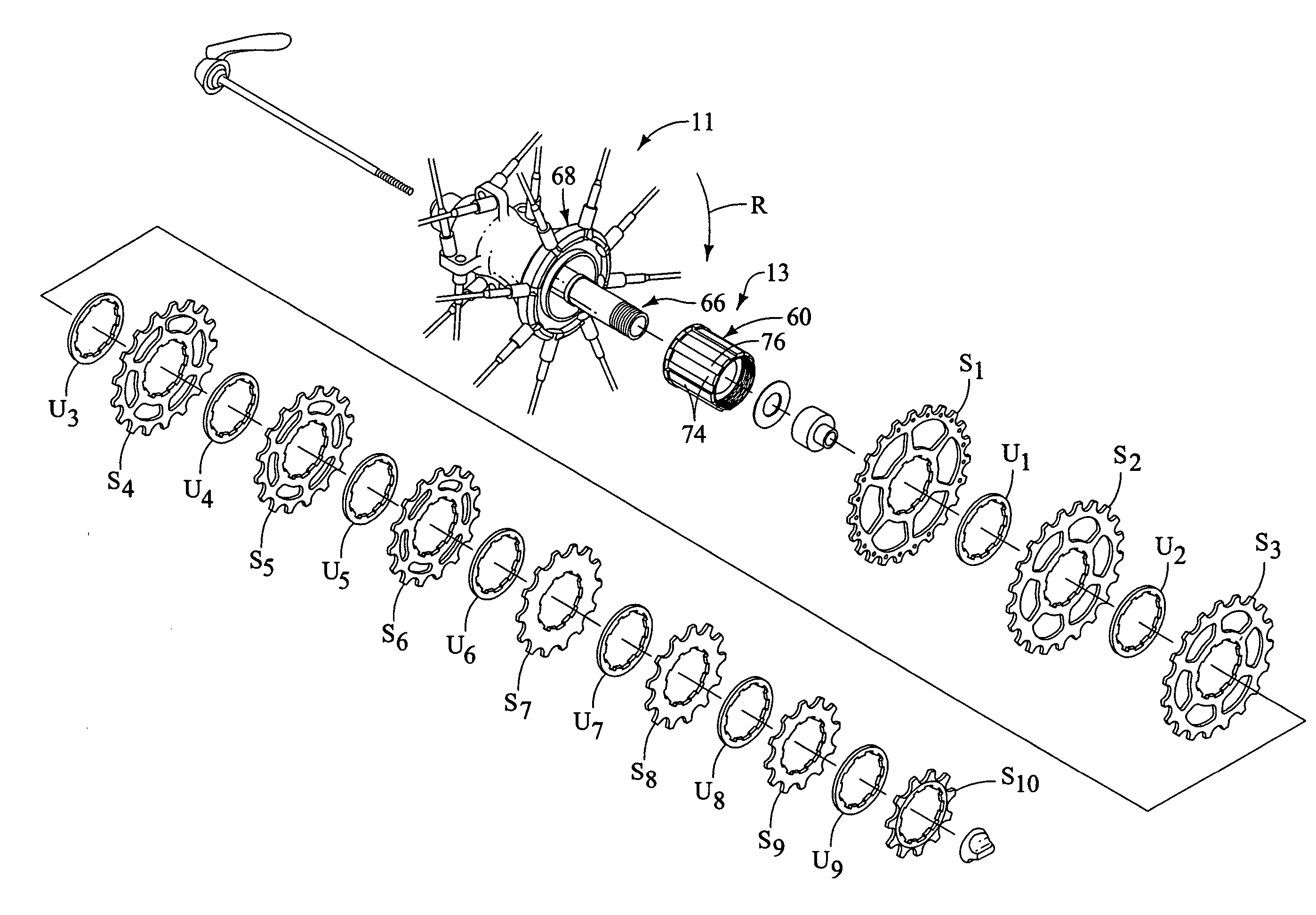
[0054] Referring now to FIG. 11, a modified bottom sprocket S1′ in accordance with a second embodiment will now be explained. The bottom sprocket S1′ replaces the bottom sprocket S1 in the rear sprocket assembly 12 of the first embodiment on the freewheel 13 of the rear hub 11. Thus, a modified rear sprocket assembly is formed when the modified bottom sprocket S1′ is substituted for the bottom sprocket S1 in the rear sprocket assembly 12 of the first embodiment.
[0055] The sprocket S1′ is identical to the sprocket S1 of the first embodiment, except the sprocket S1′ includes a single annular recess 42′ extending around the inner periphery rather than the multiple recesses 42 and 44 of the first embodiment. The recess 42′ functions the same as the multiple recesses 42 and 44 of the first embodiment. In other words, the single annular recess 42′ extending around the inner periphery has the same depth as the multiple recesses 42 and 44 of the first embodiment, but simply has a different...
PUM
 Abstract
Description
Claims
Application Information