Shift device of transmission

a technology of shifting device and transmission device, which is applied in the direction of transportation and packaging, instruments, gearing, etc., can solve the problems of not being able to accurately recognize the manipulation range without such a manipulation range indicating portion, and no longer being able to check the current manipulation state from appearance, etc., to achieve the effect of shortening the recognition tim

Inactive Publication Date: 2006-11-16
TOYOTA JIDOSHA KK
View PDF12 Cites 10 Cited by
  • Summary
  • Abstract
  • Description
  • Claims
  • Application Information

AI Technical Summary

Benefits of technology

[0016] According to the present invention, unlike the second case (the case of the second moving direction in which the movable portion moves from the first shift position toward the home position), the second shift position should be recognized in the first case (the case of the first moving direction in which the movable portion moves from the home position toward the first shift position). Therefore, if the recognition time for recognizing the second shift position is set to be short, the second shift position is quickly recognized. Thus the driver's request can appropriately be responded and the shift position can accurately be recognized. In contrast, unlike the first case, the second shift position is simply passed by the movable portion returning to the home position in the second case. Namely, recognition of the second shift position is not desired. Therefore, if the recognition time for recognizing the second shift position is extended, the second shift position is not recognized (recognized merely as a point to pass). That is, appropriate response to the driver's request is provided and the shift position can accurately be recognized.
[0018] According to the present invention, unlike the second case (the case of the second moving direction), recognition of the second shift position is desired in the first case (the case of the first moving direction). Therefore, if the recognition time for recognizing the second shift position is set to be short, the second shift position can quickly be recognized. In contrast, unlike the first case, the second shift position is simply passed by the movable portion returning to the home position in the second case. Namely, recognition of the second shift position is not desired. Therefore, if the recognition time for recognizing the second shift position is extended, recognition of the second shift position can be avoided. In this manner, in the first case, the driver can attain the second state by the transmission solely by holding the movable portion at the second shift position for a short period of time. In addition, even when a temperature of the hydraulic fluid in the shift device is low and the movable portion returns slowly from the first shift position toward the home position, the second shift position can be recognized solely as a point to pass.
[0030] According to the present invention, normally in a high vehicle speed state, modification of the power transmission state by the transmission is less likely to be requested because of drive stability of the vehicle, while it tends to be requested in a low vehicle speed state. Therefore, the predetermined recognition time is modified in accordance with the vehicle speed, so as to adapt to the driver's request. As a result, a shift device of a transmission capable of appropriately responding to the driver's request in the shift device with a momentary function can be provided.
[0031] More preferably, the modification circuit may include a circuit to make modification so as to shorten a recognition time for recognizing the second shift position when the vehicle speed is low.
[0032] According to the present invention, in the low vehicle speed state where modification of the power transmission state by the transmission tends to be requested, in particular, the second shift position can quickly be recognized and response to the driver's request can appropriately be provided. In addition, the recognition time for recognizing the shift position requested by the driver is set shorter in the low vehicle speed state than in the high vehicle speed state. Therefore, response to the driver's request can appropriately be provided in the low vehicle speed state where modification of the power transmission state by the transmission tends to be requested.
[0034] According to the present invention, the forward drive state, the neutral state, and the forward drive and engine brake actuation state can accurately be recognized in response to the request from the driver.

Problems solved by technology

Therefore, if the driver takes his hand off the lever after manipulation, the lever returns to the home position in the center, and it is no longer possible to check a current manipulation state from appearance.
Therefore, if such a momentary-type manipulation member is adopted in the shift manipulation portion, combined with discrepancy between a position shift procedure and a manipulation procedure, the driver may have uncomfortable feeling.
In particular, when the “momentary-type” manipulation member with which it is difficult to determine the manipulation range from the appearance is adopted in the shift manipulation portion, it will be difficult to have the driver accurately recognize the manipulation range without such a manipulation range indicating portion.

Method used


Image

  • Shift device of transmission
  • Shift device of transmission
  • Shift device of transmission

Examples


first embodiment

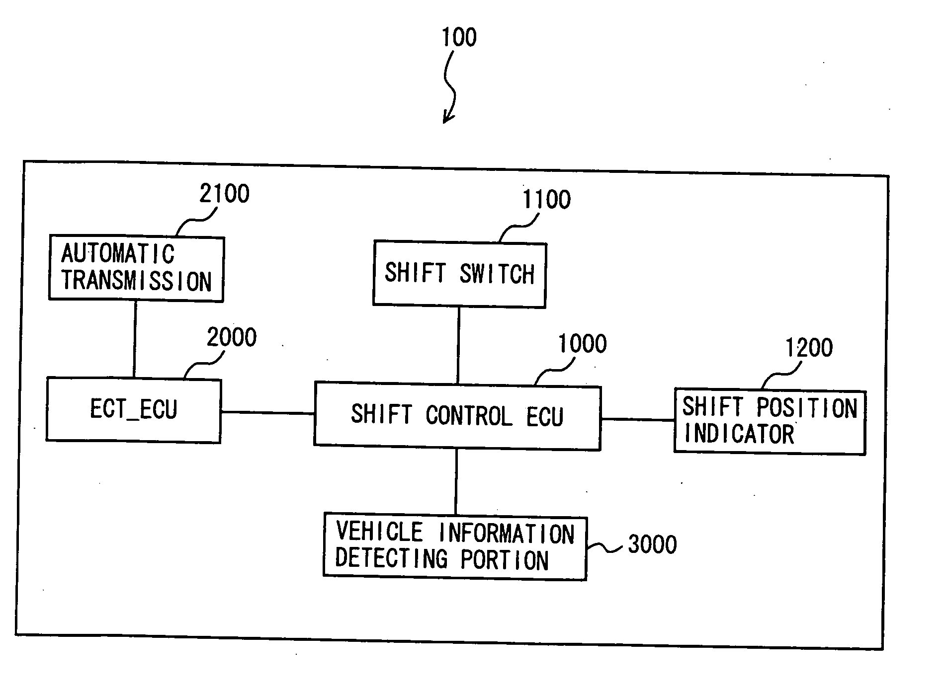
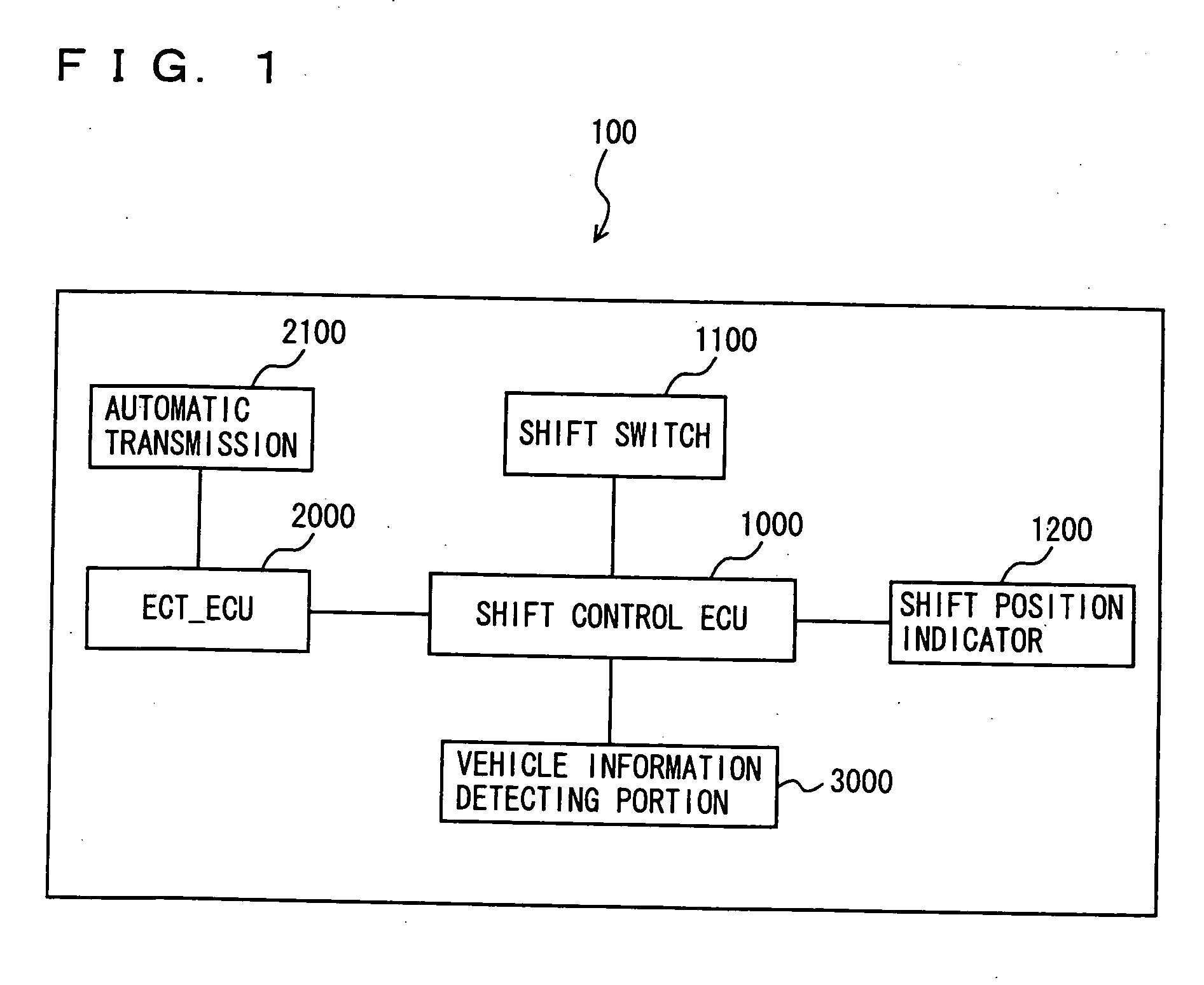
[0052] In the following, a shift manipulation system according to the first embodiment of the present invention will be described. FIG. 1 shows a control block diagram of the shift manipulation system according to the first embodiment of the present invention. As shown in FIG. 1, a shift manipulation system 100 includes a shift control ECU (Electronic Control Unit) 1000, a shift switch 1100, a shift position indicator 1200, an ECT_ECU (Electronic Controlled Automatic Transmission) 2000, an automatic transmission 2100, and a vehicle information detecting portion 3000.

[0053] Shift control ECU 1000 is connected to shift switch 1100, shift position indicator 1200, ECT_ECU 2000, and vehicle information detecting portion 3000. Shift control ECU 1000 transmits a shift control signal to ECT_ECU 2000 and outputs shift position indication information to shift position indicator 1200, based on a driver's request through manipulation of shift switch 1100. Vehicle information detecting portion ...

second embodiment

[0096] In the following, a shift manipulation system according to a second embodiment of the present invention will be described. The shift manipulation system according to the present embodiment is characterized by a shift switch 1101 shown in FIG. 9 instead of shift switch 1100 in the shift manipulation system in the first embodiment described previously. Other configuration in the second embodiment is similar to that in the first embodiment, and detailed description thereof will not be repeated.

[0097] As shown in FIG. 9, unlike shift switch 1100 in the first embodiment described previously, shift switch 1101 in the shift manipulation system according to the present embodiment attains a function as follows. Shift lever 1102 is moved along a shift-up groove 1132 as shown with an arrow 1136, so as to shift up automatic transmission 2100. In addition, shift lever 1102 is moved along a shift-down groove 1134 as shown with an arrow 1138, so as to shift down automatic transmission 2100...

third embodiment

[0100] In the following, a shift manipulation system according to a third embodiment of the present invention will be described. The shift manipulation system according to the present embodiment is different from those in the first and second embodiments in that the neutral position recognition time is modified depending on a temperature of the shift switch.

[0101]FIG. 10 is a control block diagram of a shift manipulation system 102 according to the present embodiment. In the control block diagram shown in FIG. 10, the same reference characters refer to the same or corresponding components in the control block diagram shown in FIG. 1, and functions thereof are also the same. Therefore, detailed description thereof will not be repeated.

[0102] As shown in FIG. 10, shift manipulation system 102 according to the present embodiment further includes a shift switch temperature presuming portion 1300 in addition to the configuration of shift manipulation system 100 in the first embodiment ...


PUM


Abstract

A shift control ECU includes the steps of storing a position of a shift lever; starting a count-up timer when the shift lever comes to a neutral position; and recognizing a driver's request for the neutral position when a count-up timer value attains TN(1) if the stored shift lever position is a home position and when a count-up timer value attains TN(2) if the stored shift lever position is not the home position. Here, TN(1) is set to be smaller than TN(2).

Description

[0001] This application is a divisional of and claims the benefit of priority from U.S. Ser. No. 10 / 857,973, filed Jun. 2, 2004 and is based on Japanese Patent Application No. 2003-172925 filed with the Japan Patent Office on Jun. 18, 2003, the entire contents of which are hereby incorporated by reference. FIELD OF THE INVENTION [0002] The present invention relates to a shift device for a vehicle, and more particularly to a shift device for shifting a shift position of a transmission in response to a signal obtained by detecting a state of shift manipulation by a driver. DESCRIPTION OF THE BACKGROUND ART [0003] Examples of an automatic transmission mounted on a vehicle include a gear-type automatic transmission constituted of a hydraulic coupling such as a torque converter and a gear transmission mechanism and a continuously variable automatic transmission constituted of two pulleys having an effective diameter variable depending on a hydraulic pressure and a metal belt wound on the...

Claims


Application Information

Patent Timeline
Patent Type & Authority Applications(United States)
IPC IPC(8): F16H3/44B60K20/02B60K23/00F16H59/10
CPCF16H59/0204F16H59/105F16H63/42Y10T74/19251Y10T477/60Y10T74/1926Y10T74/2003Y10T477/69Y10T477/6934
Inventor INOUE, YUJIKOBIKI, YASUSHIASAI, TOSHIHARUUCHIDA, TAKEHIROSHIMIZU, YASUO
Owner TOYOTA JIDOSHA KK
Why Eureka
Try Eureka