
Apparatus and method for detecting faults and providing diagnostics in vapor compression cycle equipment

a technology of vapor compression cycle and equipment, which is applied in the field of apparatus and method for detecting faults and providing diagnostics in vapor compression cycle equipment, can solve the problems of improper refrigerant charge, poor maintenance of many refrigeration cycles, and inability to properly charge the evaporator and/or condenser, etc., and achieves high fault detection accuracy, easy to implement hardware, and increase the efficiency of refrigeration cycles.

Inactive Publication Date: 2006-11-16
ROSSI TODD M +3
View PDF53 Cites 56 Cited by
  • Summary
  • Abstract
  • Description
  • Claims
  • Application Information

AI Technical Summary

Benefits of technology

"The present invention is an apparatus and method for detecting and diagnosing faults in refrigeration, air conditioning, or heat pump systems operating in field conditions. It measures various system parameters and calculates performance variables to determine the system's performance. This allows for accurate fault detection and reliable diagnostic solutions, regardless of the service technician's skills. The invention is affordable and can be used with any manufacturer's equipment."

Problems solved by technology

Since servicing refrigeration systems requires highly skilled technician to maintain their operation, and there are few tools available to quantify performance and provide feedback, many of refrigeration cycles are poorly maintained.
Two common degradation problems found in such commercial systems are fouling of the evaporator and / or condenser by dirt and dust, and improper refrigerant charge.
Under the best circumstances, such service is time-consuming and hit-or-miss opportunities to repair the under-performing refrigeration system.
Accordingly, sometimes professional refrigeration technicians are only called upon after a major failure of the refrigeration system occurs, and not to perform routine maintenance on such systems.
However, because of the complexity of the HVACR equipment, high equipment cost, or the inability of the refrigeration technician to comprehend and / or properly handle the equipment, such diagnostic systems have not gained wide use.

Method used

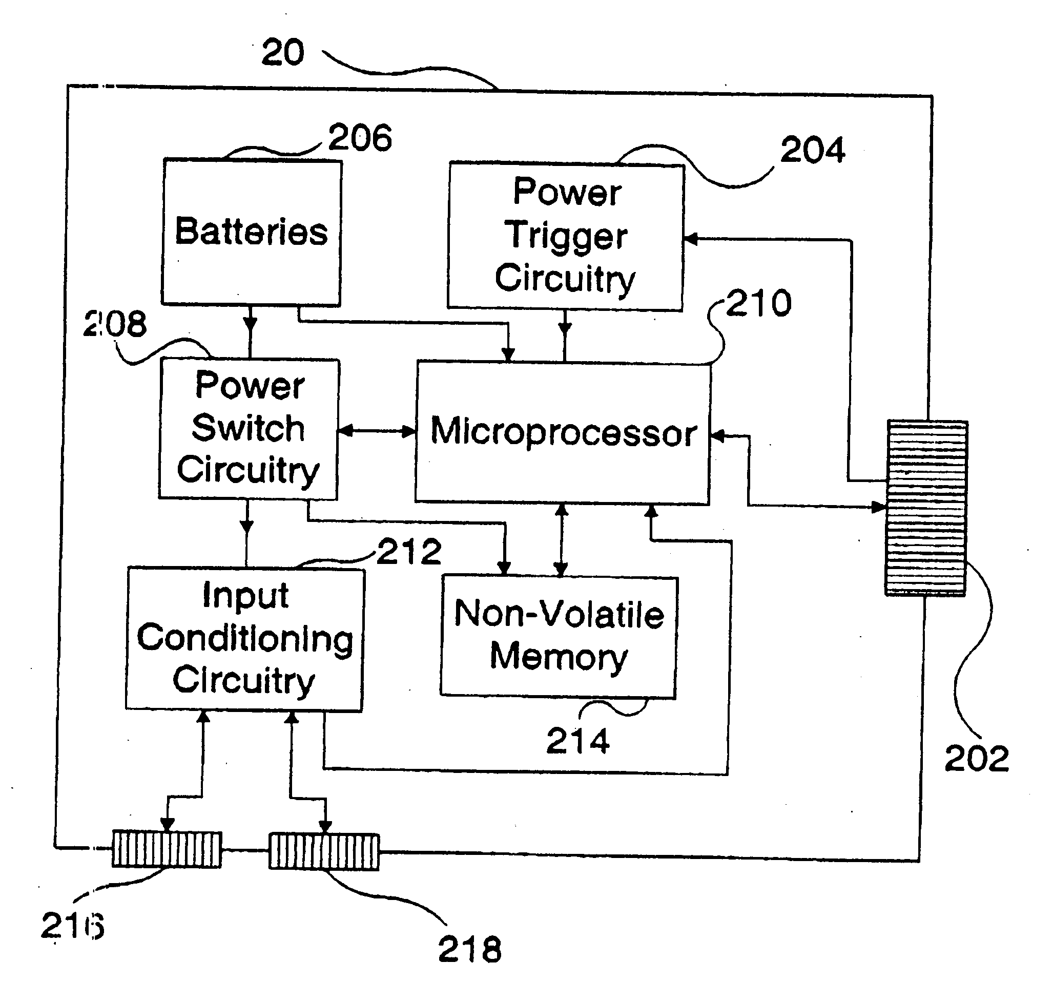
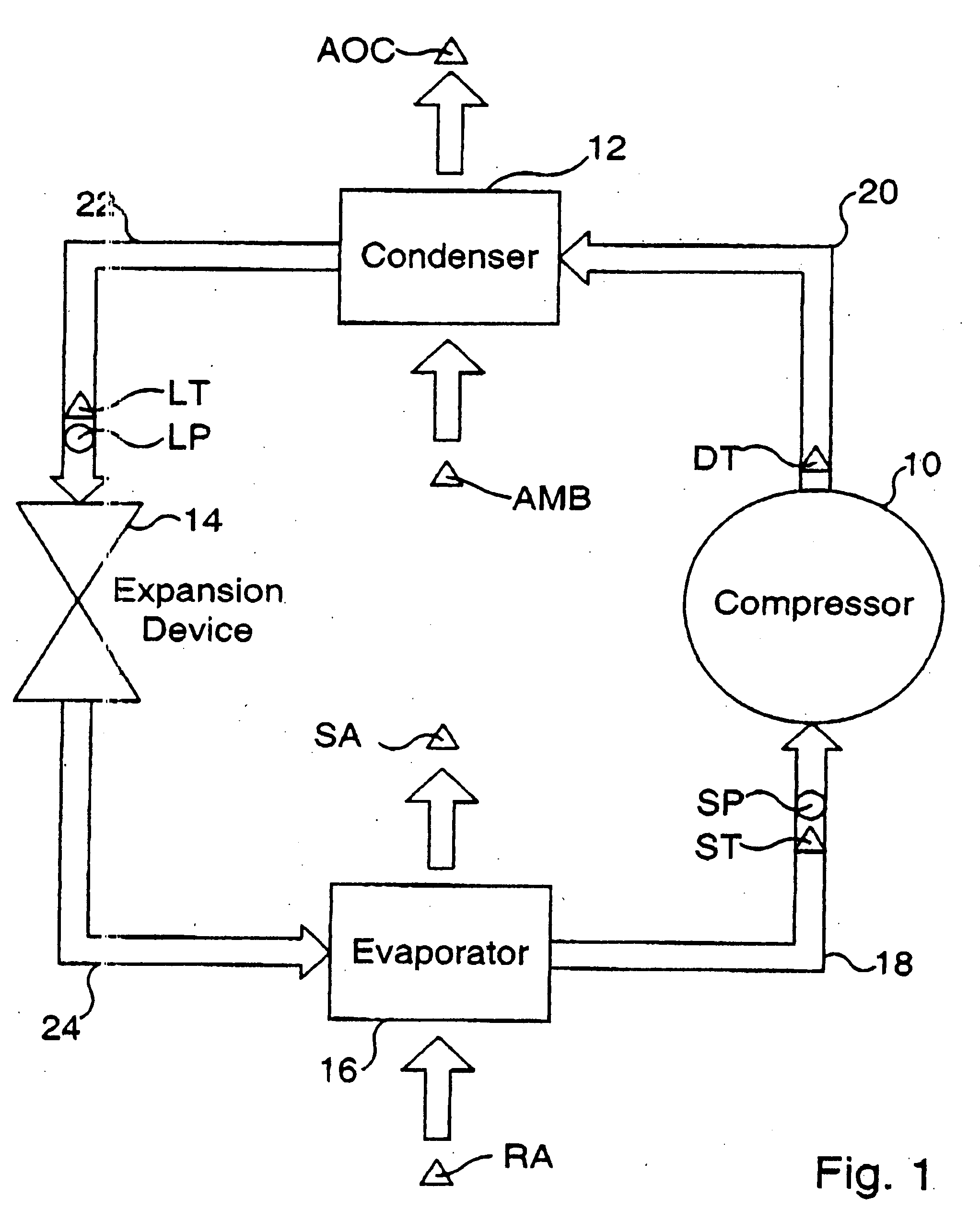
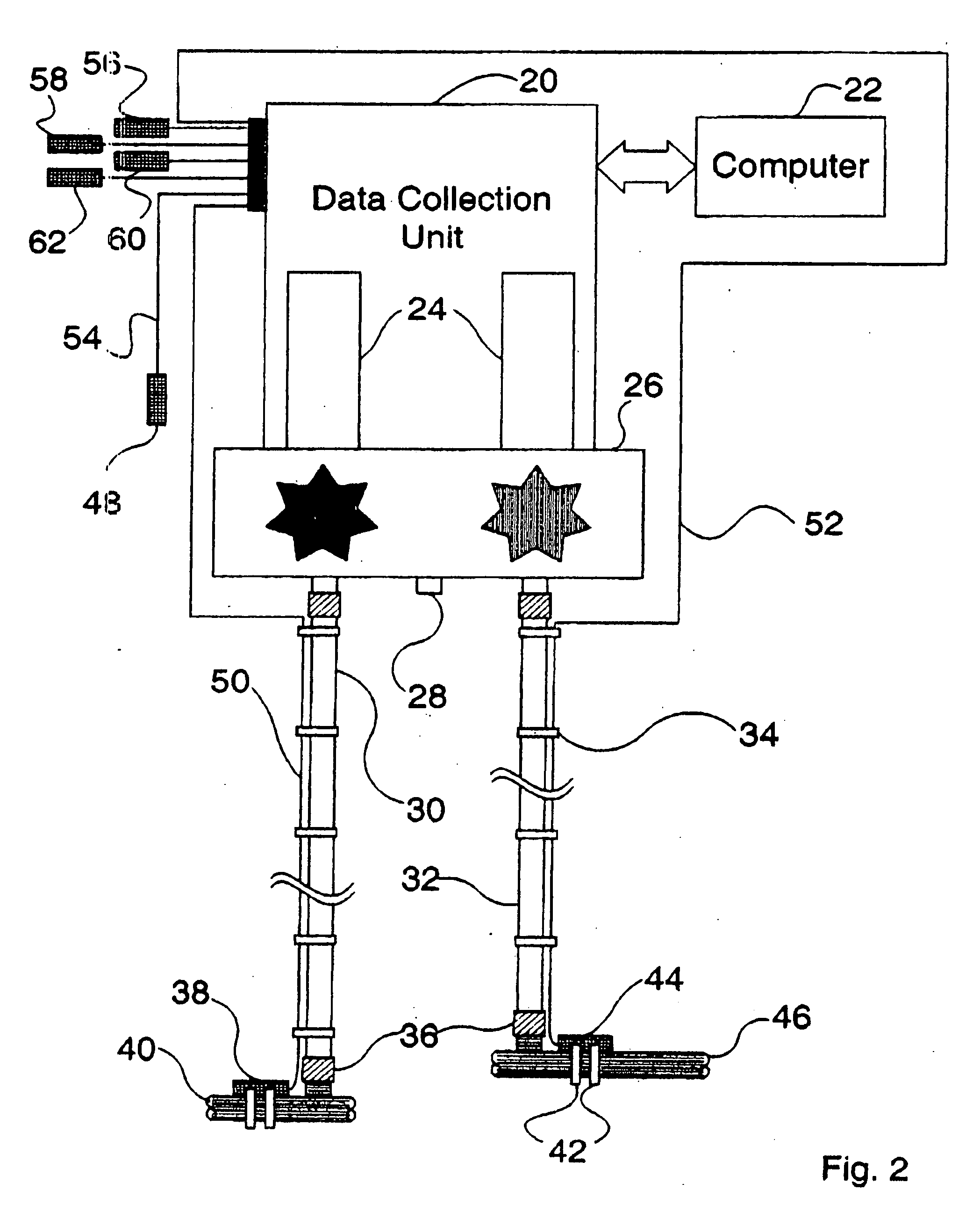

Image

  • Apparatus and method for detecting faults and providing diagnostics in vapor compression cycle equipment
  • Apparatus and method for detecting faults and providing diagnostics in vapor compression cycle equipment
  • Apparatus and method for detecting faults and providing diagnostics in vapor compression cycle equipment

Examples


Embodiment Construction

[0017] In describing preferred embodiments of the invention, specific terminology will be selected for the sake of clarity. However, the invention is not intended to be limited to the specific terms so selected, and it is to be understood that each specific term includes all technical equivalents that operate in a similar manner to accomplish a similar purpose.

[0018] The terms “refrigeration system” and “HVACR system” are used throughout this document to refer in a broad sense to an apparatus or system utilizing a vapor compression cycle to work on a refrigerant in a closed-loop operation to transport heat. Accordingly, the terms “refrigeration system” and “HVACR system” include refrigerators, freezers, air conditioners, and heat pumps.

[0019] Preferred embodiments of the present invention will now be described in detail with reference to the accompanying drawings in which a device used to carry out the method in accordance with the present invention is generally indicated by refer...


PUM


Abstract

An apparatus and method for detecting faults and providing diagnostic information in a refrigeration system comprising a microprocessor, a means for inputting information to the microprocessor, a means for outputting information from the microprocessor, and five sensors. It is emphasized that this abstract is provided to comply with the rules requiring an abstract that will allow a searcher or other reader to quickly ascertain the subject matter of the technical disclosure. It is submitted with the understanding that this abstract will not be used to interpret or limit the scope or meaning of the claims.

Description

CROSS REFERENCE TO RELATED APPLICATIONS [0001] The present application claims the benefit of U.S. Provisional Application No. 60 / 290,433 filed May 11, 2001, entitled ESTIMATING THE EFFICIENCY OF A VAPOR COMPRESSION CYCLE; and U.S. Provisional Application No. (Not Yet Known) filed Aug. 17, 2001, under Express Mail # EJ045546604US, entitled VAPOR COMPRESSION CYCLE FAULT DETECTION AND DIAGNOSTICS in the name of Todd Rossi, Dale Rossi and Jon Douglas.FIELD OF THE INVENTION [0002] The present invention relates generally to heating / ventilation / air conditioning / refrigeration (HVACR) systems and, more specifically, to detecting faults in a system utilizing a vapor compression cycle under actual operating conditions and providing diagnostics for fixing the detected faults. BACKGROUND OF THE INVENTION [0003] Air conditioners, refrigerators and heat pumps are all classified as HVACR systems. The most common technology used in all these systems is the vapor compression cycle (often referred to ...

Claims


Application Information

Patent Timeline
Patent Type & Authority Applications(United States)
IPC IPC(8): G06F15/00F24F11/00F25B49/00F25B49/02
CPCF24F11/0086F25B2700/21172F25B49/005F25B49/02F25B2500/19F25B2600/19F25B2600/21F25B2700/02F25B2700/1931F25B2700/1933F25B2700/195F25B2700/2106F25B2700/21151F25B2700/21161F25B2700/21163F24F2011/0067F24F11/30F24F11/54F24F11/38
Inventor ROSSI, TODD M.ROSSI, DALEDOUGLAS, JONATHAN D.STOCKMAN, TIMOTHY P.
Owner ROSSI TODD M
Learn More