
System and method for distributing data over a computer network

a computer network and data technology, applied in the field of systems for distributing data, can solve the problem that the bandwidth of the computer system at another location is only sufficient, and achieve the effect of short time duration

Inactive Publication Date: 2006-11-16
NETWORK FOUNDATION TECHNOLOGIES
View PDF29 Cites 79 Cited by
  • Summary
  • Abstract
  • Description
  • Claims
  • Application Information

AI Technical Summary

Benefits of technology

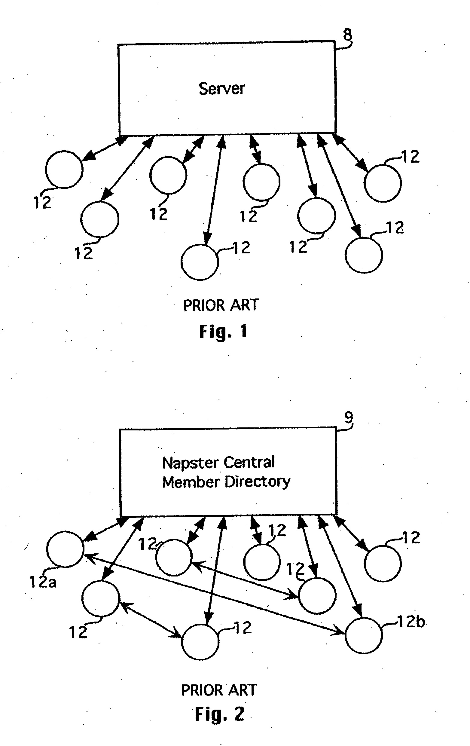
[0016] To help understand streaming media in more detail, it is helpful to review the traditional Internet distribution method. Each node (whether it is a server node or a user node) in a computer network has a unique identification (sometimes referred to as an “IP” address) associated with it. On the Internet, the unique address may be referred to as a Uniform Resource Locator (“URL”). A user desiring to obtain data from a particular server enters that server's URL into the user's browser program. The browser program causes a connection request signal to be sent over the Internet to the server. If the server has the capacity to accept the connection, the connection is made between the server and the user node (files requested by the user are typically transmitted by the server in full to the user node and the browser program may store the files in buffer memory and display the content on the user's computer system monitor—some files may be more permanently stored in the computer system's memory for later viewing or playing.) The connection with the server is typically terminated once the files have been received at the user node (or the connection may be terminated a short time thereafter). Either way, the connection is usually of a very short time duration.

Problems solved by technology

A computer system at another location may have only sufficient bandwidth to effectively exchange data with only one other computer system.

Method used


Image

  • System and method for distributing data over a computer network
  • System and method for distributing data over a computer network
  • System and method for distributing data over a computer network

Examples


Embodiment Construction

[0091] Detailed embodiments of the present invention are disclosed herein; however, it is to be understood that the disclosed embodiments are merely illustrative of the invention that may be embodied in various forms. In addition, each of the examples given in connection with the various embodiments of the invention are intended to be illustrative, and not restrictive. Further, the figures are not necessarily to scale, some features may be exaggerated to show details of particular components. Therefore, specific structural and functional details disclosed herein are not to be interpreted as limiting, but merely as a representative basis for teaching one skilled in the art to variously employ the present invention.

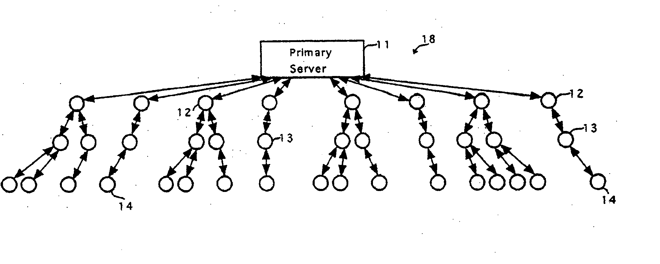
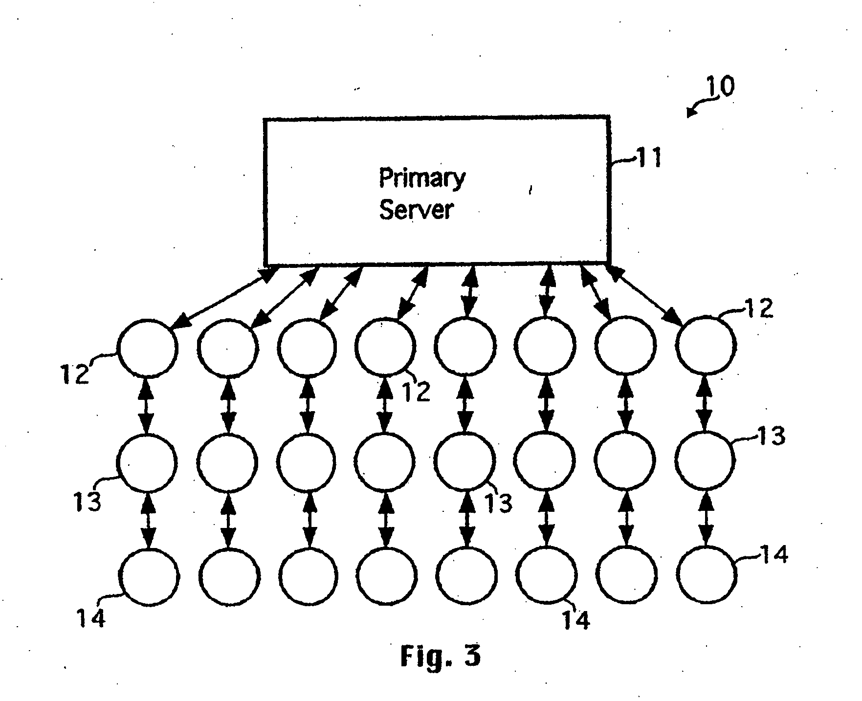
[0092] Referring now to FIG. 3, an illustration of a linear propagation arrangement 10 of a computer network according to an embodiment of the present invention is shown. In this embodiment, the primary server node (or simply, server) 11 provides content data (e.g., stream...


PUM


Abstract

A system and method are provided for delivery of broadcast data over an augmented tree network that includes a content server, a tree server, an augmentation server and at least one node. The content server streams a fraction of the broadcast data to the tree server, and streams a complement to the fraction of the broadcast data to the augmentation server. A node connects to the tree server, thereby receiving the fraction of the broadcast data, the fraction having a positive value less than one. The node connects to the augmentation server, thereby receiving the complement to the fraction of the broadcast data from the augmentation server. The node assembles the fraction of the broadcast data with the complement to the fraction of the broadcast data to reassemble the broadcast data, whereby broadcast data is delivered to the node.

Description

[0001] This patent application claims priority to U.S. Provisional Patent Application No. 60 / 778,359 filed Mar. 3, 2006, the entire disclosure of which is incorporated herein by reference. This application is a continuation-in-part of U.S. patent application Ser. No. 11 / 179,041 filed Jul. 11, 2005, U.S. patent application Ser. No. 11 / 179,063 filed Jul. 11, 2005, U.S. patent application Ser. No. 11 / 176,956 filed Jul. 7, 2005, and U.S. patent application Ser. No. 09 / 952,907 filed Sep. 13, 2001, (collectively, the “Copending Patent Applications”). The entire disclosures of the Copending Patent Applications are hereby incorporated herein by reference in their entirety.FIELD OF THE INVENTION [0002] Various embodiments of the present invention relate to systems for distributing data (e.g., content data) over a computer network and methods of arranging nodes for distribution of data (e.g., content data) over a computer network. In one example (which example is intended to be illustrative a...

Claims


Application Information

Patent Timeline
Patent Type & Authority Applications(United States)
IPC IPC(8): G06F15/173
CPCH04L12/1836H04L67/1089H04L12/1854H04L12/1868H04L41/12H04L63/02H04L63/0428H04N21/238H04N21/4788H04L67/16H04L67/104H04L67/06H04L67/1095H04L67/1097H04L67/1091H04L67/1048H04L12/185H04L67/51H04L41/122
Inventor O'NEAL, MICHAELTALTON, JOHN P.STROUD, BEN S.NORMAN, CHARLES R.FRANCIS, JOEL A.
Owner NETWORK FOUNDATION TECHNOLOGIES
Learn More