

Bracket having a three-layered base
Inactive Publication Date: 2006-11-23
MORSE MICHAEL G
View PDF26 Cites 32 Cited by
- Summary
- Abstract
- Description
- Claims
- Application Information
AI Technical Summary
Benefits of technology
[0017] To counter the above shortcomings, the inventor developed brackets that, among other things, greatly increase the lateral load-carrying capacity of the guardrail post-to-deck connection. These brackets replace the lag bolt and augment the carriage bolt or through-bolt connection to create a much stronger connection that directs the force into the contiguous deck members, absorbing and distributing the ener
Problems solved by technology
These are the daily risks that they try to guard against.
However, the injuries that are most likely to take everything they have worked so hard for occur after they have packed up their tools, turned their work over to the homeowner, and are working on the next job.
Years later, after they have moved on, timber has shrunk and settled, connections have loosened, and catastrophe occurs.
A deck railing fails, giving way and spilling the occupants from the deck.
Wedding receptions and graduations turn from festive occasions into tragic news events.
A few years will pass, depositions will be taken, and the contractor will lose everything.
Because deck railings are hard pressed to handle the loads placed on them during their full service life.
The inventor's te
Method used
View moreImage
Smart ImageViewing Examples

Examples
 PUM
 Abstract
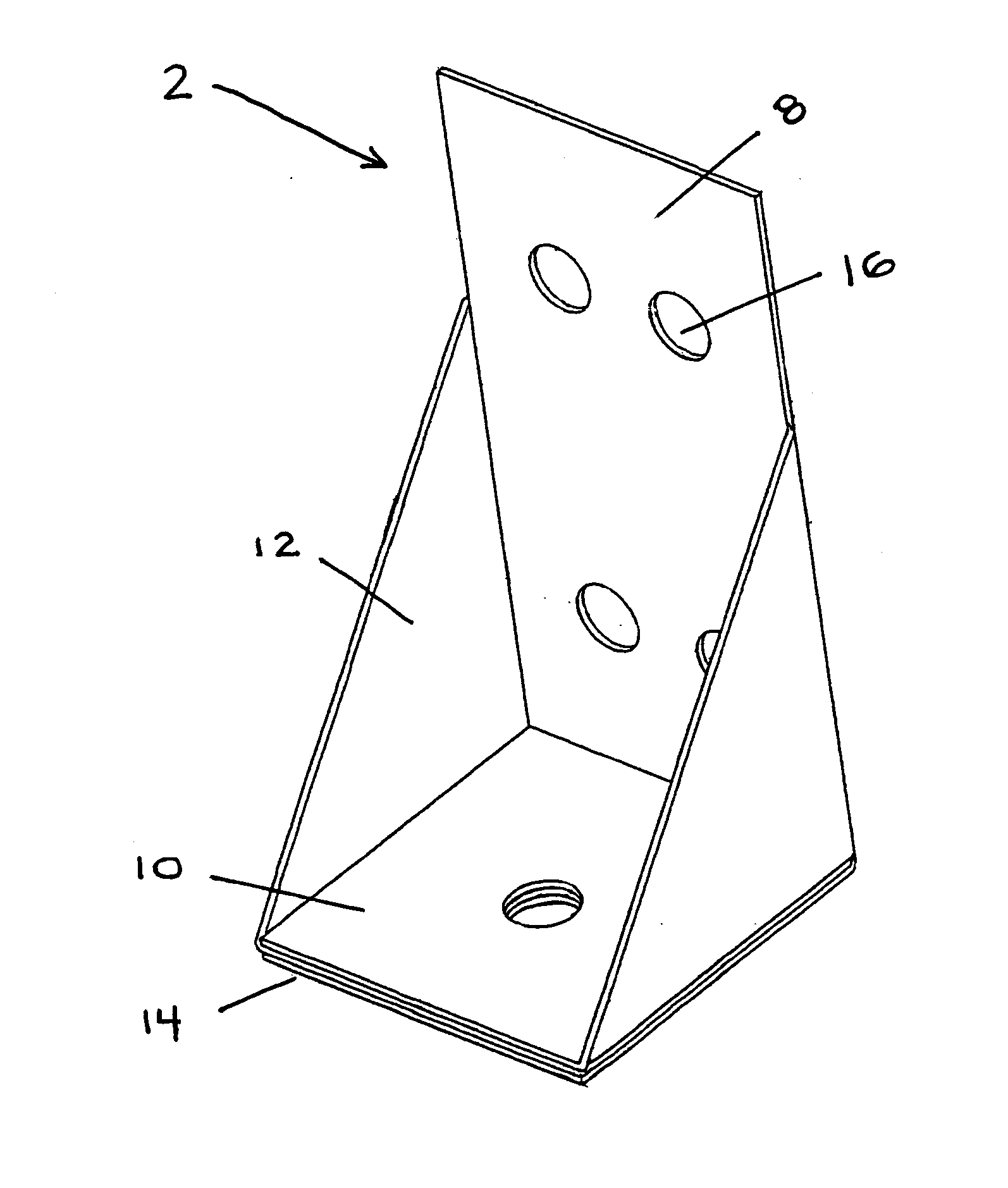
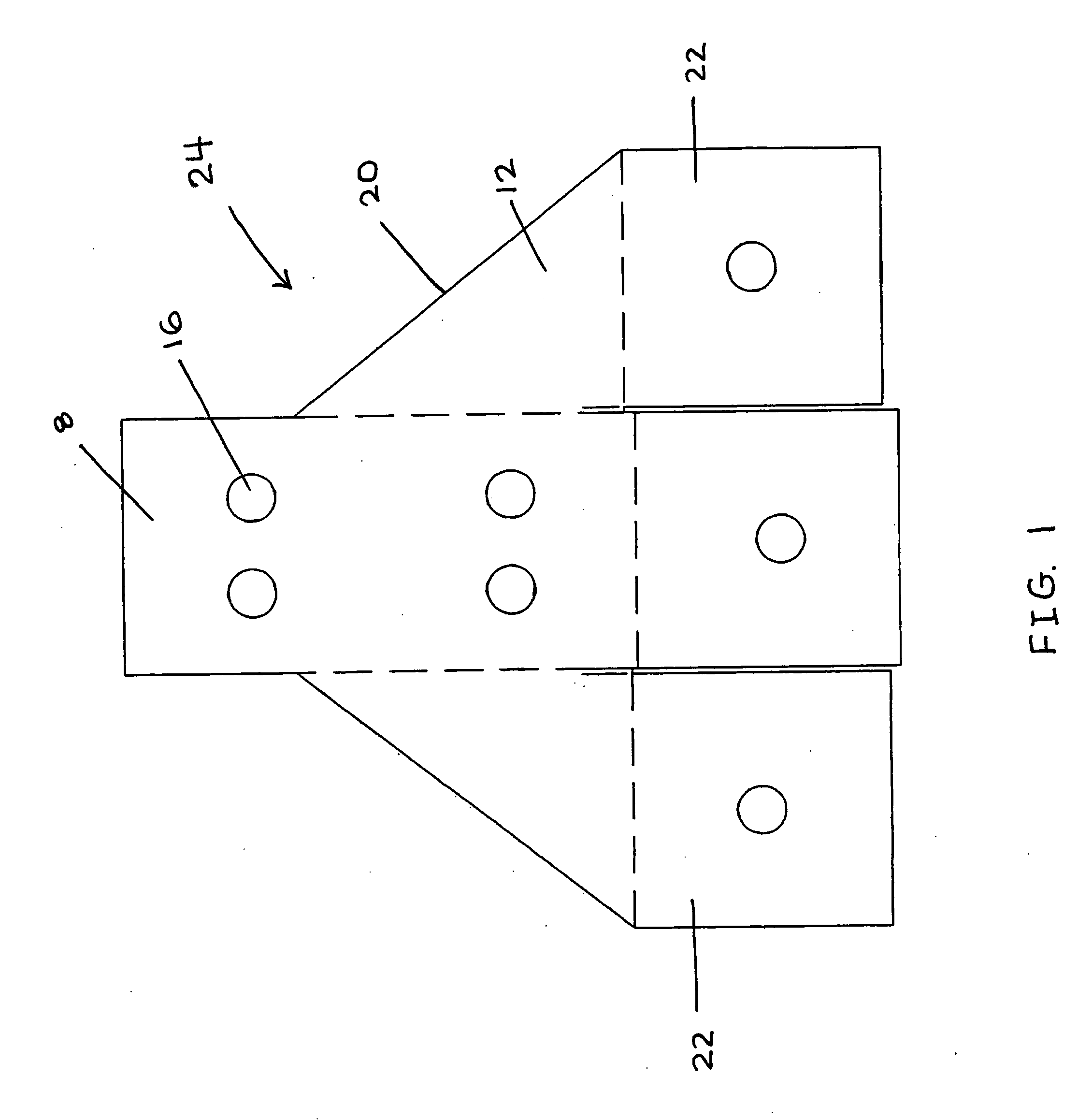
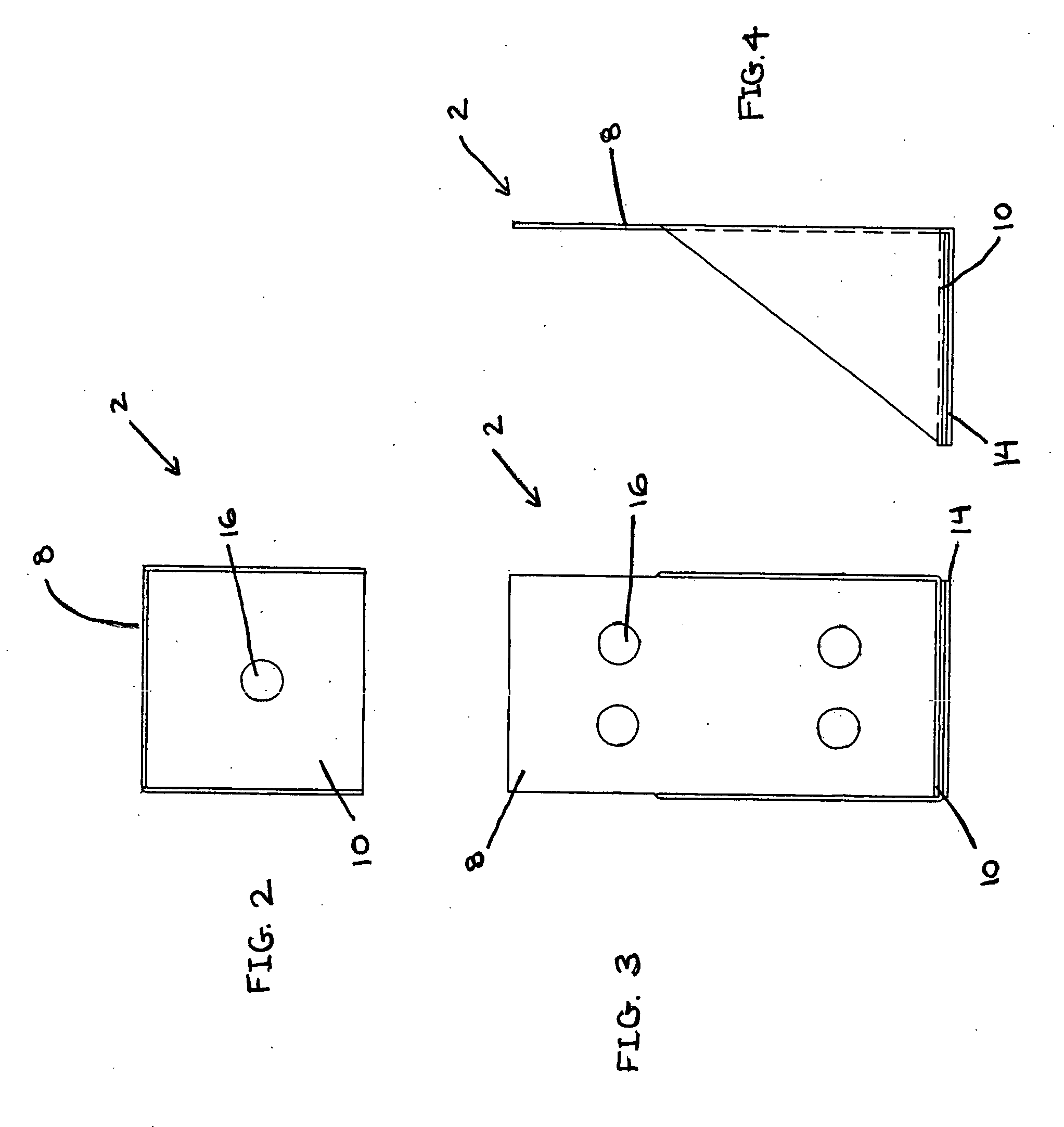
A bracket having a long leg and a base wherein the base has at least two layers. A preferred bracket has lateral support pieces connecting the long leg and the base. A method of holding a second portion of a structure which is subject to a pulling or pushing force tending to separate it from a first portion of the structure is also disclosed. The method comprises providing an “L”-shaped bracket having a long leg and a base, laterally attaching the long leg of the bracket to a first portion of the structure and laterally attaching the base of the bracket to the second portion of the structure.
Description
CROSS-REFERENCE TO RELATED APPLICATIONS [0001] This application claims the benefit of the filing date of provisional application Ser. No. ______ filed ______.STATEMENT REGARDING FEDERALLY SPONSORED RESEARCH OR DEVELOPMENT [0002] (Not applicable) REFERENCE TO SEQUENTIAL LISTING, A TABLE, OR A COMPUTER PROGRAM LISTING APPENDIX SUBMITTED ON A COMPACT DISC [0003] (Not applicable) BACKGROUND OF THE INVENTION [0004] 1) Field of the Invention [0005] This invention is concerned with brackets which add security to those portions of structures which are subjected to forces which tend to pull or push them away from the other portions of the structure and to methods of using the brackets. [0006] 2) Description of the Related Art [0007] Every deck builder knows full well the risks inherent in his or her occupation. Most injuries are related to builders getting cut, smashing body parts, getting nicked with saws, or stepping on nails. These are the daily risks that they try to guard against. Howev...
Claims
Login to View More Application Information
Patent Timeline
 IPC IPC(8): E04B1/38
CPCE04B1/2608
Inventor MORSE, MICHAEL G.
Owner MORSE MICHAEL G