Stable Rotary Drill Bit

Inactive Publication Date: 2006-11-23
REEDHYCALOG UK
View PDF10 Cites 32 Cited by
  • Summary
  • Abstract
  • Description
  • Claims
  • Application Information

AI Technical Summary

Benefits of technology

[0012] The outer surface of the outer regions of the additional blades may be rendered of improved resistance to wear. This could be achieved for example by mounting suitabl

Problems solved by technology

As a result, during drilling, the outer regions of the additional blades can bear against the surface of the formation being drilled,

Method used


Image

  • Stable Rotary Drill Bit
  • Stable Rotary Drill Bit
  • Stable Rotary Drill Bit

Examples


Embodiment Construction

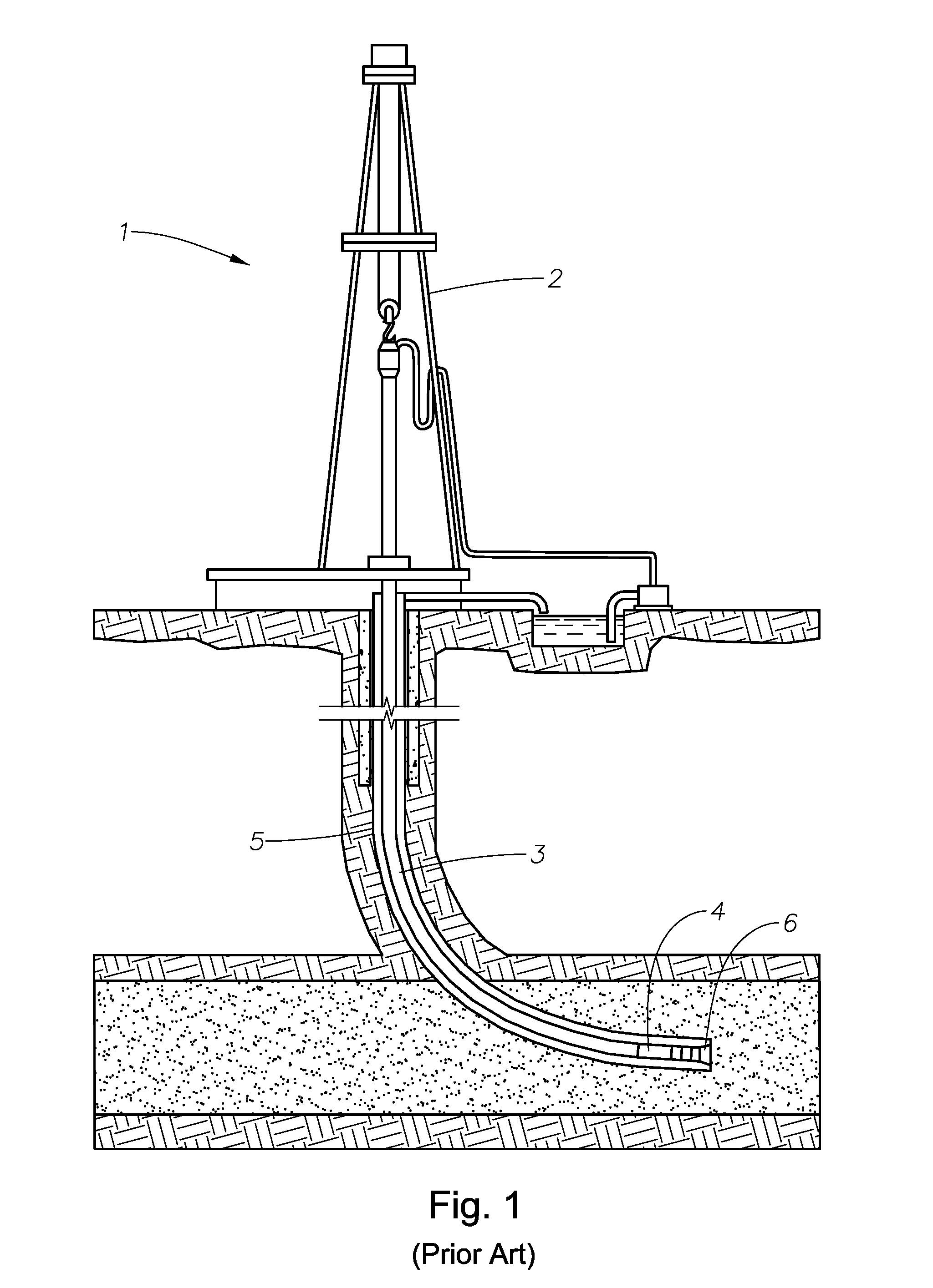
[0021] Referring first to FIG. 1, a drilling system 1, is shown and comprises a drill rig 2, with a drill string 3, and a drill bit 6, located within borehole 5. The drill bit 6 may be rotated from the surface by rotation of the drill string. Alternatively or additionally the drill bit 6, may be rotated by a downhole motor or turbine 4.

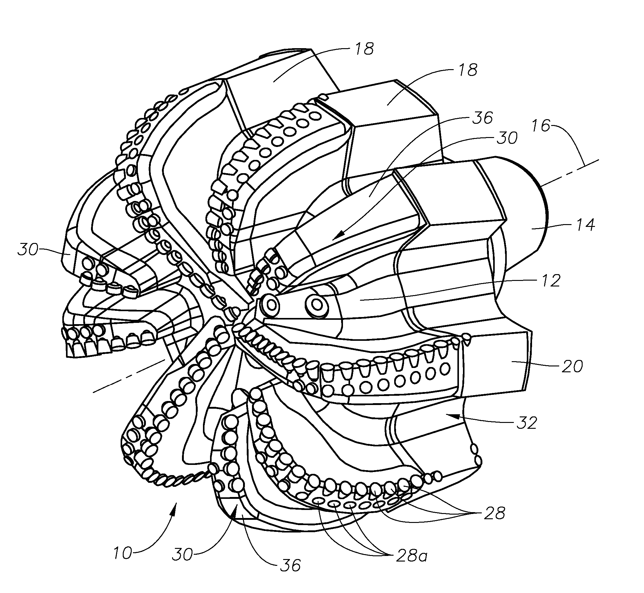
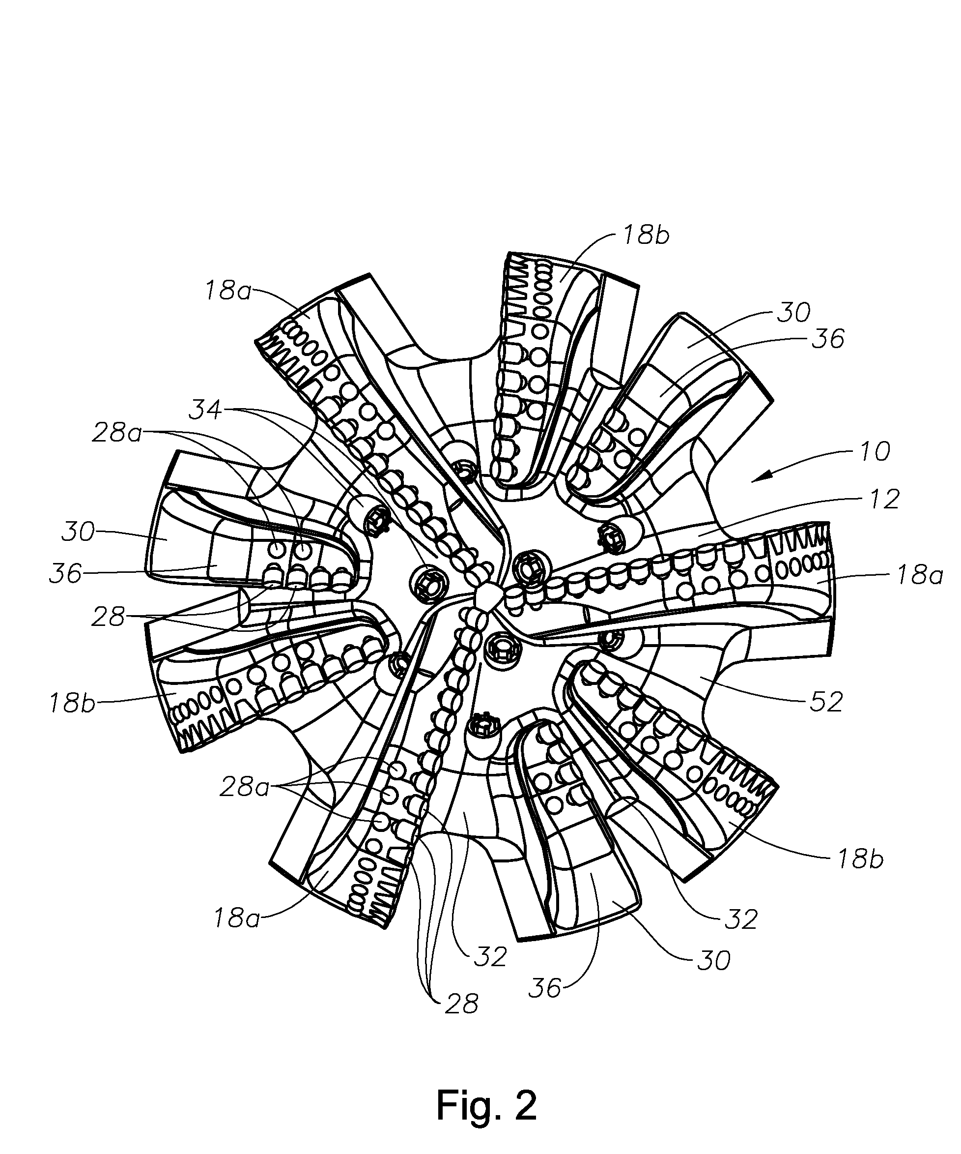
[0022] Referring to FIGS. 2 to 5 there is shown a drill bit comprising a bit body 10 having a front face 12 and a connection region 14 designed to allow the bit to be connected to other downhole components, in use, to allow the bit to be driven for rotation about its centerline 16 and to allow an axially directed load to be applied thereto.

[0023] Mounted on the bit body 10 are a number of upstanding main blades 18, the main blades 18 upstanding from the front face 12 of the bit body 10. The main blades 18 include a first plurality of blades 18a which extend from the center line 16, of the bit to the gauge region 20 thereof, and a second plurality of...


PUM


Abstract

A drill bit comprises a bit body having a plurality of upstanding main blades formed thereon. The main blades have a plurality cutting elements mounted thereon, and they are shaped such that a cutting profile of the bit includes a nose portion, an inner cone region located radially inwards of the nose portion and an outer region located radially outwards of the nose portion. The bit further has at least one additional blade. The additional blade carrying cutting elements located radially inwards of the outer region of the cutting profile, but being substantially free of cutting elements located in the outer region of the cutting profile.

Description

BACKGROUND OF THE INVENTION [0001] This invention relates to a rotary drill bit that is vibrationally stable, and in particular to a rotary drill bit suitable for use in the formation of subterranean well bores. [0002] The cost of drilling a borehole in the subsurface formations of the Earth is dependent on the length of time taken to drill the borehole to the desired depth. The time spent drilling is in turn determined by the rate of penetration and the number of times the drill bit has to be changed in order to achieve the target depth. [0003] A known form of drill bit for use in the formation of subterranean well bores comprises a bit body having formed thereon a series of upstanding blades. Each blade is provided with a series of cutting elements. The cutting elements each typically comprise a substrate of, for example, tungsten carbide to which is bonded a table of a superhard material, for example in the form of polycrystalline diamond. Between the blades are formed flow chann...

Claims


Application Information

Patent Timeline
IPC IPC(8): E21B10/08E21B10/42E21B10/43E21B10/54
CPCE21B10/42E21B10/54E21B10/43
Inventor JOHNSON, SIMON C.
Owner REEDHYCALOG UK
Why Eureka
Try Eureka