Non-spill container with flow control structure including baffle and elastic membrane having normally-closed pinholes

a flow control device and non-spill container technology, applied in the field of non-spill beverage containers, can solve the problems of reducing the resilient force needed to close the slit flap, slits and/or become obstructed, and the slit flaps cannot close, so as to achieve the effect of facilitating fluid flow rate, limiting fluid pressure, and enhancing the “no drip” characteristi

Inactive Publication Date: 2006-11-23
INSTA MIX INC SUBSIDIARY A DBA UMIX +1
View PDF54 Cites 37 Cited by
  • Summary
  • Abstract
  • Description
  • Claims
  • Application Information

AI Technical Summary

Benefits of technology

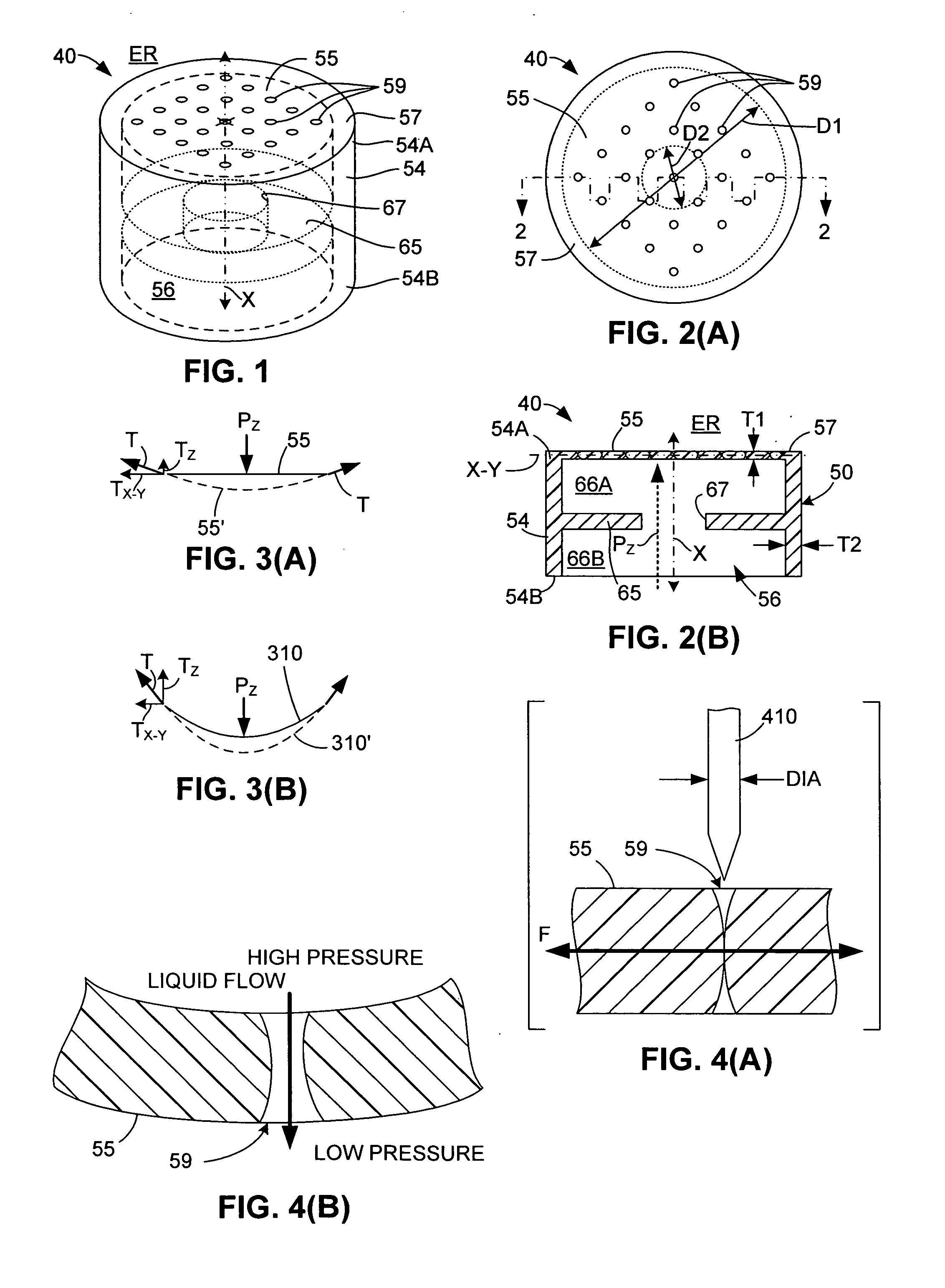
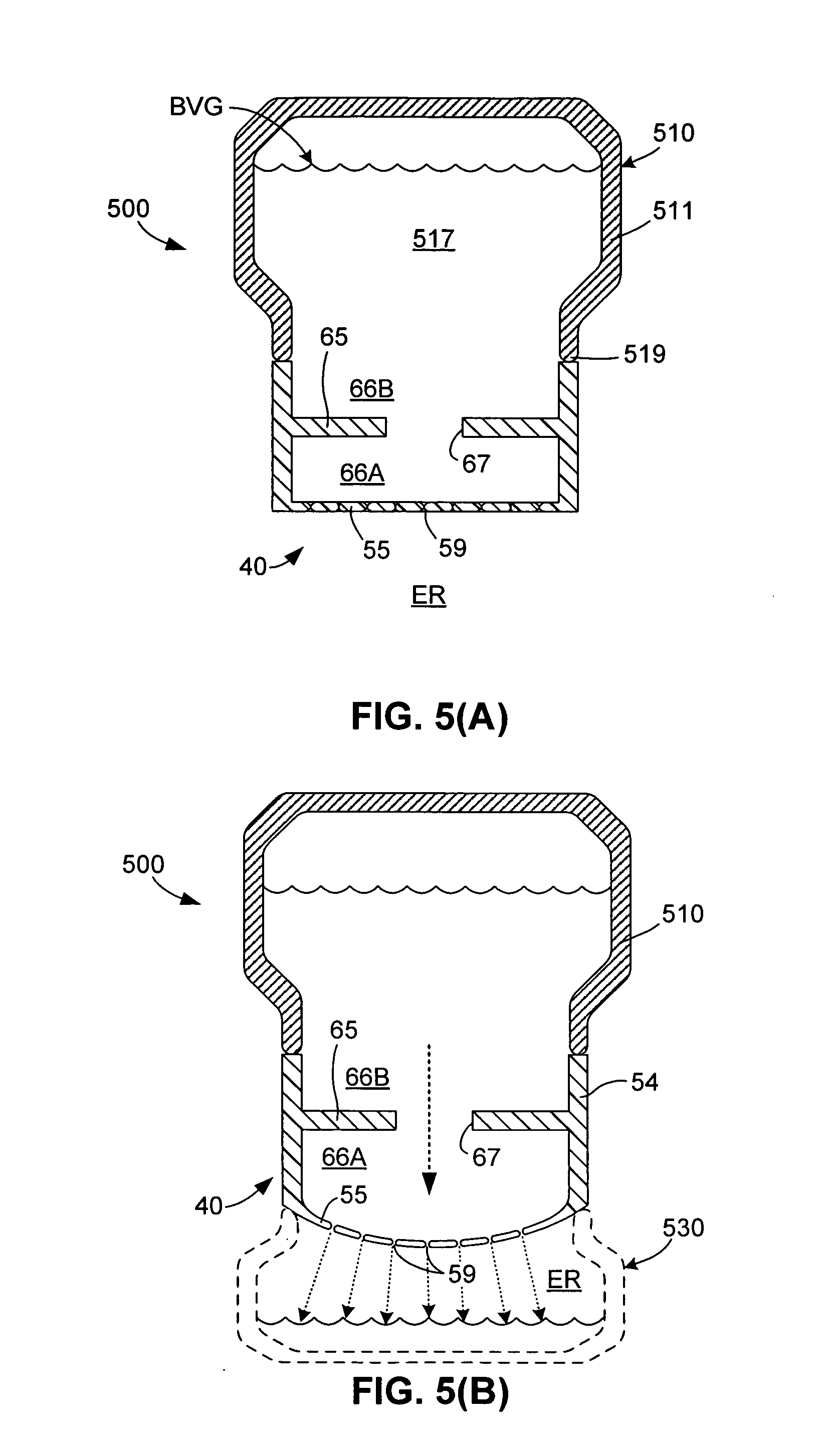
[0007] The present invention is directed to a flow control structure for a non-spill beverage container (e.g., a child sippy cup or an adult travel mug) that includes a tube-like spout defining a relatively wide flow channel, a membrane extending across an end of the flow channel, and a baffle supported in the flow channel that provides a small opening between a beverage storage chamber and the membrane. The membrane is formed from a suitable elastomeric material (e.g., soft rubber, thermoplastic elastomer, or silicone) that is punctured to form multiple, substantially round pinholes that remain closed to prevent fluid flow through the membrane and flow channel under normal atmospheric conditions (i.e., while the membrane remains non-deformed), thereby providing a desired “no drip” characteristic. The baffle further enhances this “no drip” characteristic by acting to limit fluid pressure in the region between the baffle and the membrane (i.e., in the presence of a higher fluid pressure downstream of the baffle). Conversely, when subjected to such an applied pressure differential (e.g., when sucked on by a child), the membrane stretches (deforms), thereby causing some or all of the pinholes to open and to facilitate fluid flow rate through the membrane, which is substantially unimpeded by the baffle under these conditions. Because the amount that the pinholes open, and the associated fluid flow through the pinholes, is related to the applied pressure differential, the present invention provides a flow control structure that automatically adjusts its fluid flow rate to the applied suction. In addition, because the pinholes are substantially round, the pinholes resist the clogging and tearing problems associated with slit-type flow control structures.
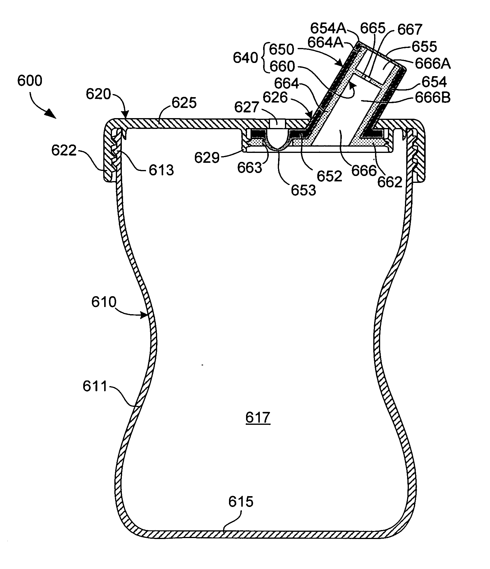
[0008] According to another embodiment of the present invention, a non-spill beverage container includes a container body, a cap mounted over an open end of the container body, and a flow control structure mounted on the cap such that a spout of the flow control structure extends through an opening in the cap. The flow control structure includes an outer, relatively flexible member that includes a tube-like outer spout portion and the membrane, and an inner, relatively rigid member that includes the baffle. The inner member includes a base that is screwed, snap-coupled or otherwise secured to the cap, and an inner spout portion that forms the flow channel. The outer member mounts over the inner spout portion such that the membrane is positioned at the upper end of the spout. Because the membrane is located at the end of the spout, when a user finishes drinking and the pinholes close, beverage that may be retained in the flow channel is prevented from dripping from the spout by the membrane, thus avoiding the dripping problem associated with conventional non-spill beverage containers.

Problems solved by technology

One problem associated with conventional non-spill cups is that the elastomeric material used to form the slit-type “no drip” flow control valves can fatigue in the region of the slits and / or become obstructed over time, and the resulting loss of resilience can cause leakage when the slit flaps fail to fully close after use.
This failure of the slit flaps to close can be caused by any of several mechanisms, or a combination thereof.
First, repeated shearing forces exerted at the end of each slit due to repeated use can cause tearing of the elastomeric material in this region, thereby reducing the resilient forces needed to close the slit flaps after use.
Second, thermal cycling or mechanical cleaning (brushing) of the elastomeric material due, for example, to repeated washing, can cause the elastomeric material to become less elastic (i.e., more brittle), which can also reduce the resilience of the slit flaps.
Third, solid deposits left by liquids passing through the slits can accumulate over time to impede the slit flaps from closing fully.
A second problem associated with conventional non-spill cups is that the “no drip” flow control valves are typically located inside the short, straw-like drinking spout such that a small, open upper section of the spout is located above the valve.

Method used


Image

  • Non-spill container with flow control structure including baffle and elastic membrane having normally-closed pinholes
  • Non-spill container with flow control structure including baffle and elastic membrane having normally-closed pinholes
  • Non-spill container with flow control structure including baffle and elastic membrane having normally-closed pinholes

Examples


Embodiment Construction

[0024]FIG. 1 is a perspective view showing a flow control structure 40 according to a generalized embodiment of the present invention, and FIGS. 2(A) and 2(B) show flow control structure 40 in top plan and cross-sectional side views, respectively, where FIG. 2(B) is taken along section line 2-2 of FIG. 2(A).

[0025] Flow control structure40 includes a molded (first) member 50 including a tube-like spout 54 defining a substantially cylindrical flow channel 56, a membrane 55 mounted on an upper (first) end 54A of spout 54, and a baffle 65 mounted inside flow channel 56 between upper end 54A and a lower end 54B of spout 54. Spout 54 is a relatively rigid (i.e., compared to membrane 55) tube-like structure extending generally along a central axis X between upper end 54A and lower end 54B of spout 54. As indicated in FIG. 2(A), in one embodiment spout 54 has a circular cross section having an inner diameter (width) D1. In other embodiments, spout 54 may have, for example, an oval, square ...


PUM


Abstract

A flow control structure for a non-spill beverage container that includes a tube-like spout defining a flow channel, and a substantially flat membrane supported by the spout over one end of the flow channel, and an annular baffle mounted in the flow channel. The membrane punctured to form multiple, substantially round pinholes arranged in a two-dimensional pattern that remain closed to prevent fluid and air flow under normal atmospheric conditions, and open and to facilitate fluid flow rate through the membrane under an applied pressure differential (e.g., when sucked on by a child). The annular baffle defines an opening that limits differential pressures applied to the membrane when not in use, thereby acting in combination with the membrane to prevent leaks. The baffle opening is also sized such that, during normal use (e.g., sucked on by a child), substantial flow is generated through the membrane.

Description

FIELD OF THE INVENTION [0001] The present invention relates to fluid flow control devices for non-spill beverage containers, and more specifically it relates to “no drip” flow control structures for, e.g., child sippy cups and adult “travel” mugs. RELATED ART [0002] Sippy cups and travel mugs represent two types of non-spill beverage containers that utilize flow control devices to control the ingestion of beverage in response to an applied sucking force. Sippy cups are a type of spill-resistant container typically made for children that include a cup body and a screw-on or snap-on lid having a drinking spout molded thereon. An inexpensive flow control element, such as a soft rubber or silicone outlet valve, is often provided on the sippy cup lid to control the flow of liquid through the drinking spout and to prevent leakage when the sippy cup is tipped over when not in use. Adult non-spill “travel” mugs are usually fabricated from a thermally insulating material, and have a narrow s...

Claims


Application Information

Patent Timeline
Patent Type & Authority Applications(United States)
IPC IPC(8): B65D51/16A47G19/22
CPCA47G19/2272
Inventor HOLLEY, JAMES W. JR.
Owner INSTA MIX INC SUBSIDIARY A DBA UMIX
Why Eureka
Try Eureka