
Discharge prevention circuit and electronic equipment provided with the discharge prevention circuit

a discharge prevention circuit and electronic equipment technology, applied in the direction of electric variable regulation, process and machine control, instruments, etc., can solve the problems of consuming a lot of power, affecting the operation of communication services, and the number of communication equipment connected to one power unit is limited, so as to achieve the effect of less energy

Active Publication Date: 2006-11-23
NEC CORP
View PDF1 Cites 139 Cited by
  • Summary
  • Abstract
  • Description
  • Claims
  • Application Information

AI Technical Summary

Benefits of technology

[0011] The invention has been developed in view of circumstances as described in the foregoing, and it is one of the objects of the invention to provide a discharge prevention circuit which may use a small current transformer. It is also another object of the invention to provide a small scale discharge prevention circuit and provide a discharge prevention circuit which consumes less energy.

Problems solved by technology

In this case, the number of units of the communication equipment connectable to one power unit is limited by the power supply capacity of the power unit and the power consumption of the respective units of communication equipment.
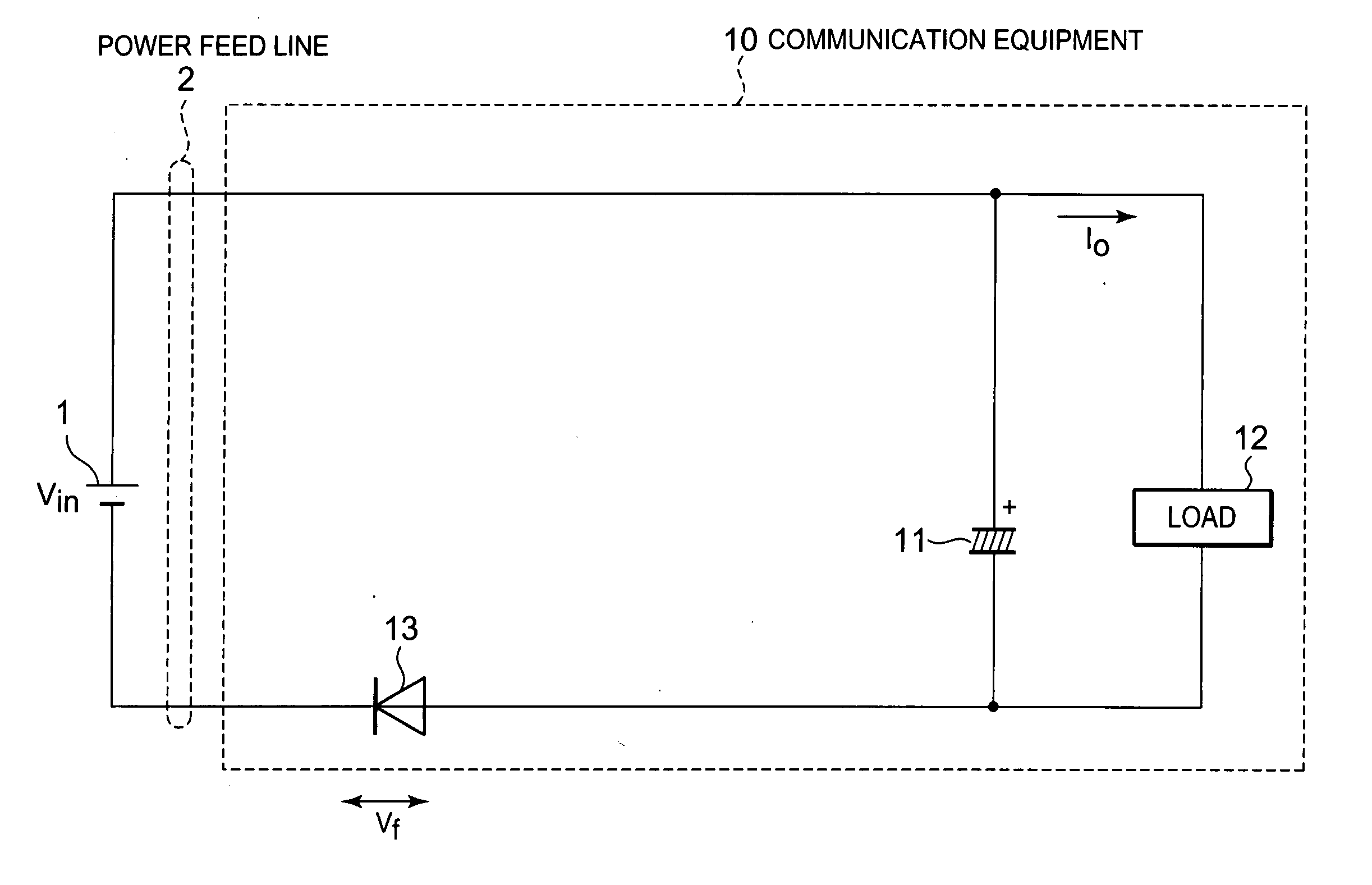
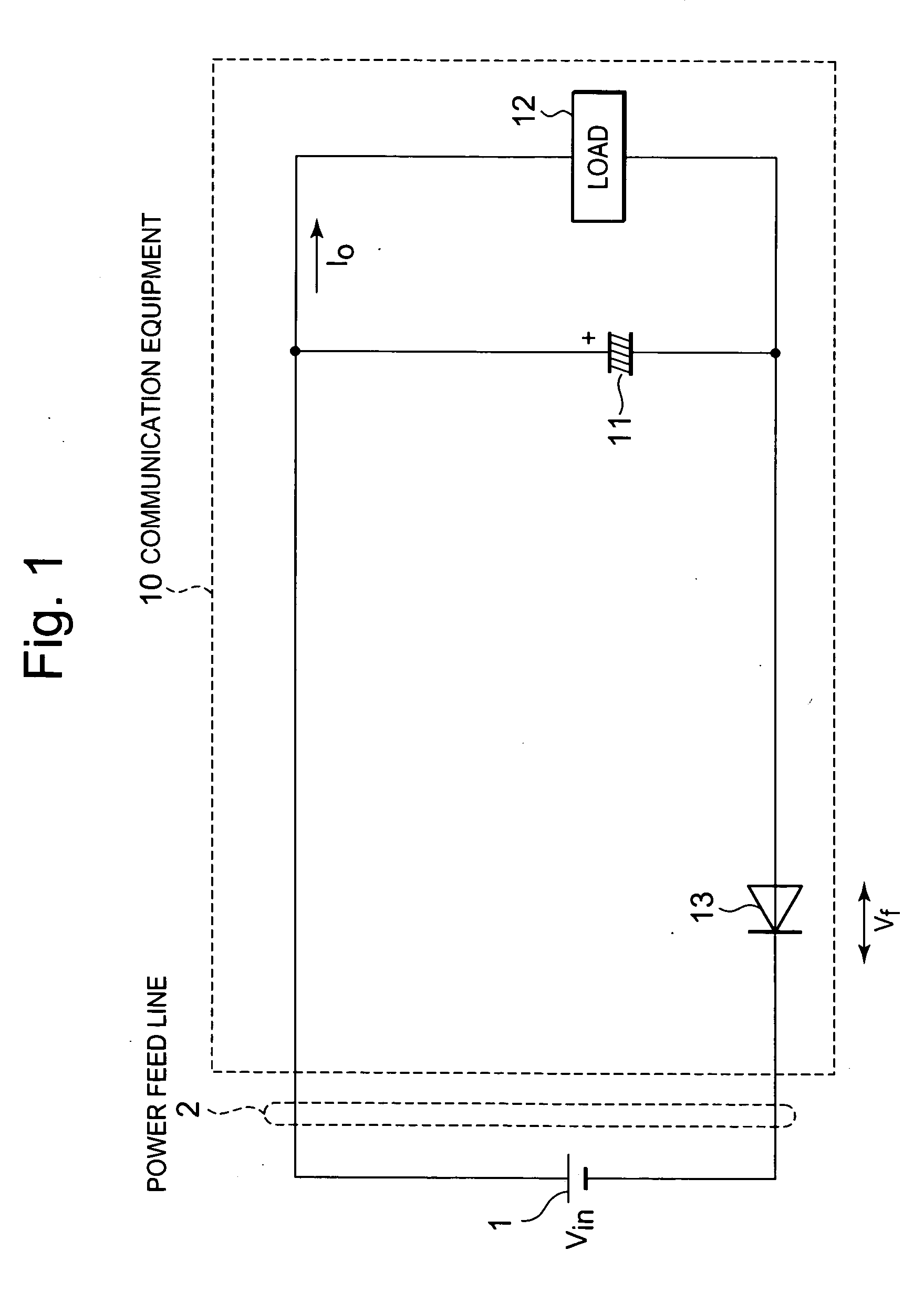
When an add-on unit of communication equipment is sequentially and additionally connected to a power feed line while a DC power supply voltage is supplied from the power feed line to already installed units of the communication equipment, a capacitor incorporated in the power input portion of the add-on unit of the communication equipment is charged, and then, the DC power supply voltage of the power feed line momentarily drops, thereby causing at times a problem in that the already installed units of the communication equipment stop operation, resulting in stoppage of operation of communication service.
Accordingly, it is difficult to provide equipment consuming a lot of power with the discharge prevention circuit disclosed in Japanese Laid-open patent No. 315201 / 2002.
However, the related discharge prevention circuits described as above have the following problems.

Method used


Image

  • Discharge prevention circuit and electronic equipment provided with the discharge prevention circuit
  • Discharge prevention circuit and electronic equipment provided with the discharge prevention circuit
  • Discharge prevention circuit and electronic equipment provided with the discharge prevention circuit

Examples


Embodiment Construction

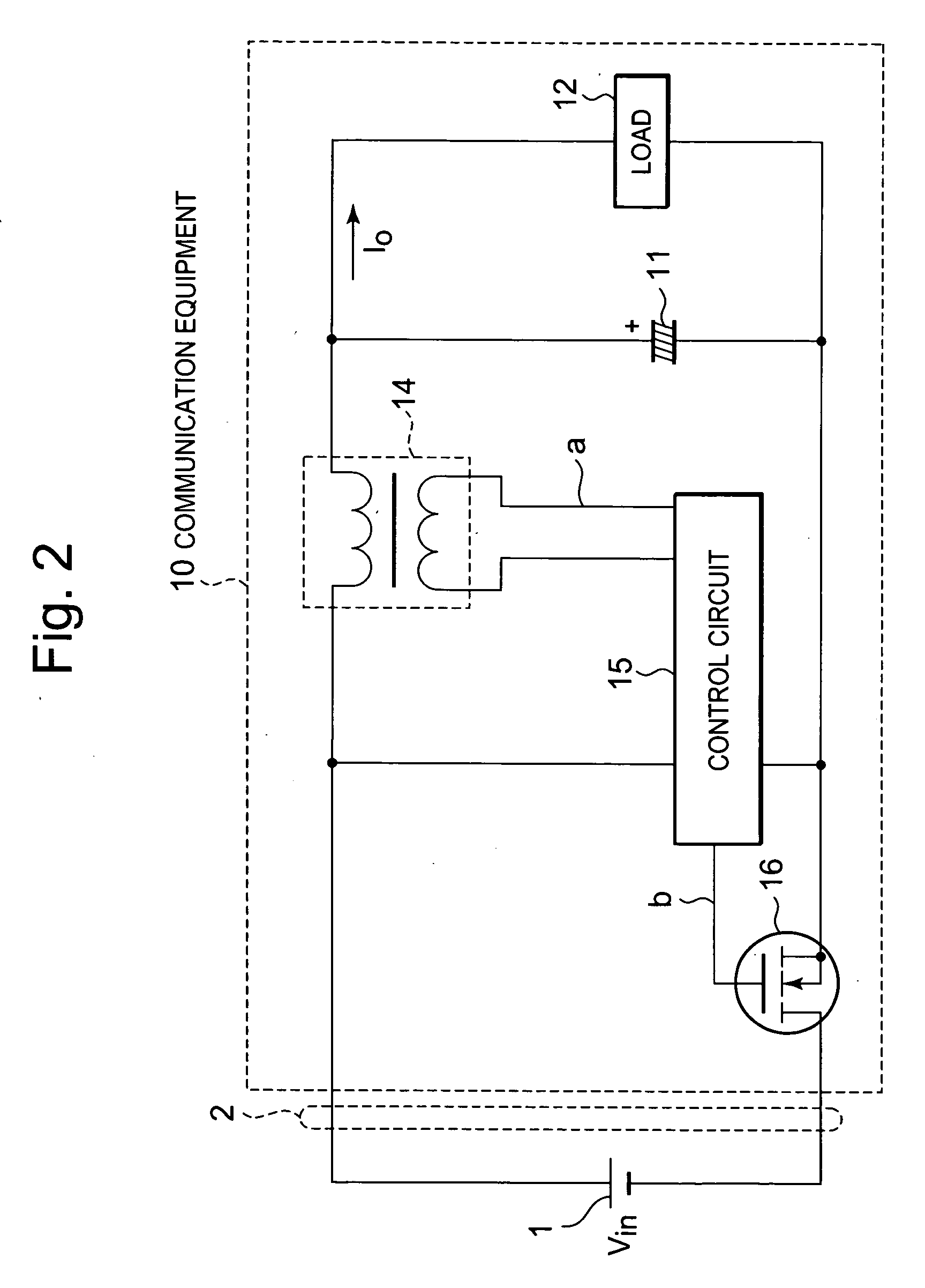
[0033] Hereinafter, exemplary embodiments of the present invention will now be described in detail with reference to the accompanying drawings. The described exemplar embodiments are intended to assist in understanding the invention, and are not intended to limit the scope of the invention in any way.

[0034] According to one of the aspect of the invention, a discharge prevention circuit wherein a MOSFET (a switching means) is turned into the OFF state when a discharge current of a capacitor is detected by a current transformer, thereby turning a state of connection between the capacitor and a power feed line into the OFF state.

[0035]FIG. 3 is a circuit diagram showing an electrical configuration of the principal part of electronic equipment provided with a first exemplary embodiment of a discharge prevention circuit.

[0036] As shown in the FIG. 3, the electronic equipment according to the first exemplary embodiment is communication equipment 20 connected to a DC power unit 1 via a ...


PUM


Abstract

A discharge prevention circuit and electronic equipment with the discharge prevention circuit are provided. The discharging prevention circuit includes a first power line, a second power line, a capacitor, a current detector and a switch. The first and second power lines directly or indirectly connect a power feed line to a load. The capacitor and the current detector are directly or indirectly connected in series between the first and second power lines. The switch is disposed in the first or second power line. The current detector detects at least charging current to the capacitor and discharging current from the capacitor. And if the current detector detects discharging current from the capacitor, the switch acts to stop current flow between the capacitor and the power feed line through the switch.

Description

CROSS-REFERENCE TO RELATED PATENT APPLICATION [0001] This application claims the priority from Japanese Patent Application No. 144457 / 2005, filed on May 17, 2005, in the Japanese Patent Office, the disclosure of which is incorporated herein by reference in its entirety. BACKGROUND OF THE INVENTION [0002] The invention relates to a discharge prevention circuit, electronic equipment provided with the discharge prevention circuit, and, in particular, to a discharge prevention circuit for preventing a capacitor from being discharged. The invention may be used in a system where a DC power supply voltage is supplied from a power feed line to electronic equipment having the capacitor for storing energy at the power input, and similar electronic equipment may be sequentially and additionally connected to or disconnected from the power feed line. [0003] As the demand for cellular phones and connection with the Internet have increased in recent years, communication companies such as Internet ...

Claims


Application Information

Patent Timeline
Patent Type & Authority Applications(United States)
IPC IPC(8): H05B37/02
CPCH02H3/18
Inventor OKABE, YOSHIHARUMUTO, TAKANORI
Owner NEC CORP
Learn More