
Multi-frequency antenna

Inactive Publication Date: 2006-11-23
HON HAI PRECISION IND CO LTD
View PDF19 Cites 35 Cited by
  • Summary
  • Abstract
  • Description
  • Claims
  • Application Information

AI Technical Summary

Benefits of technology

[0006] An object of the present invention is to provide a multi-frequency antenna which can integrate the antenna for WWAN and the antenna for WLAN together, thereby reducing the installation space of the antenna and the antenna having the excellent performance.

Problems solved by technology

However, the two individual antennas will inevitably occupy more space than a single antenna in general.

Method used


Image

  • Multi-frequency antenna
  • Multi-frequency antenna
  • Multi-frequency antenna

Examples


Embodiment Construction

[0014] Reference will now be made in detail to the preferred embodiment of the present invention.

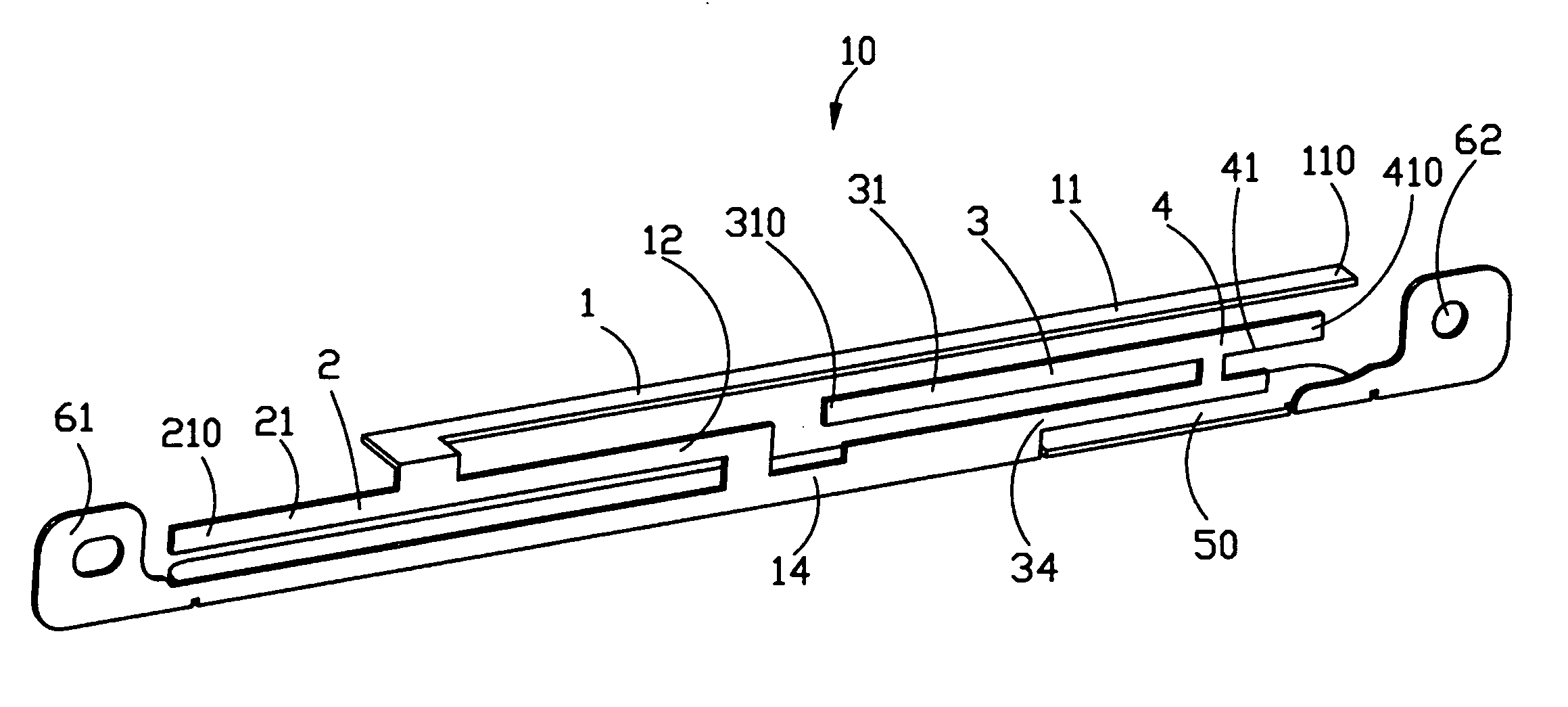
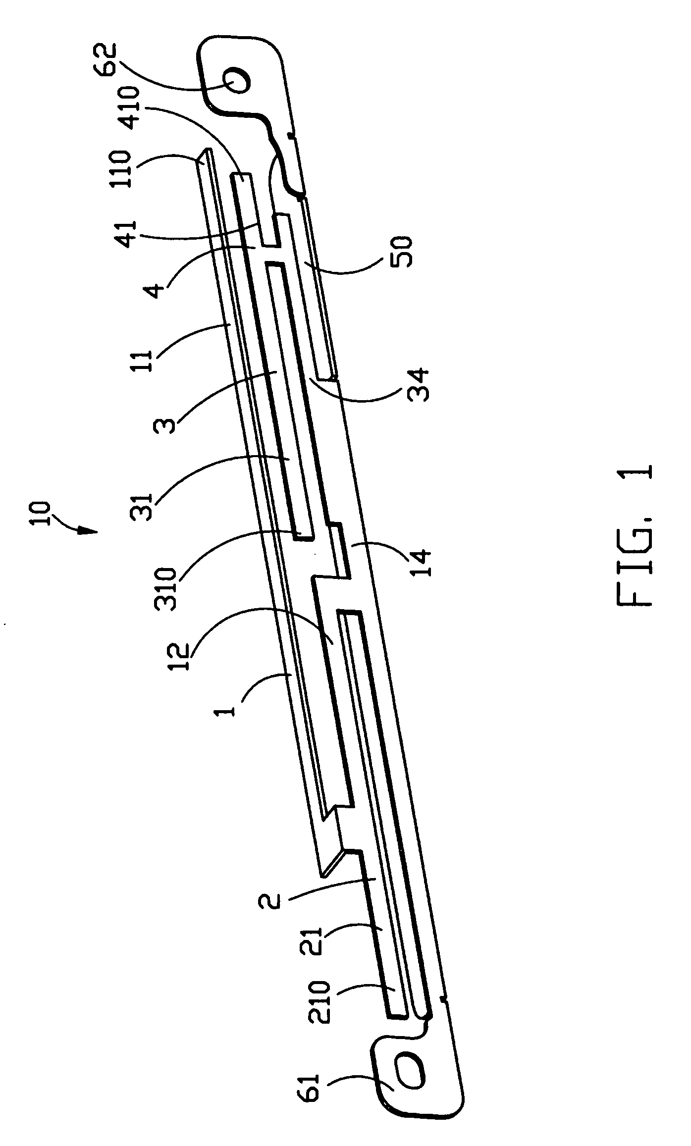
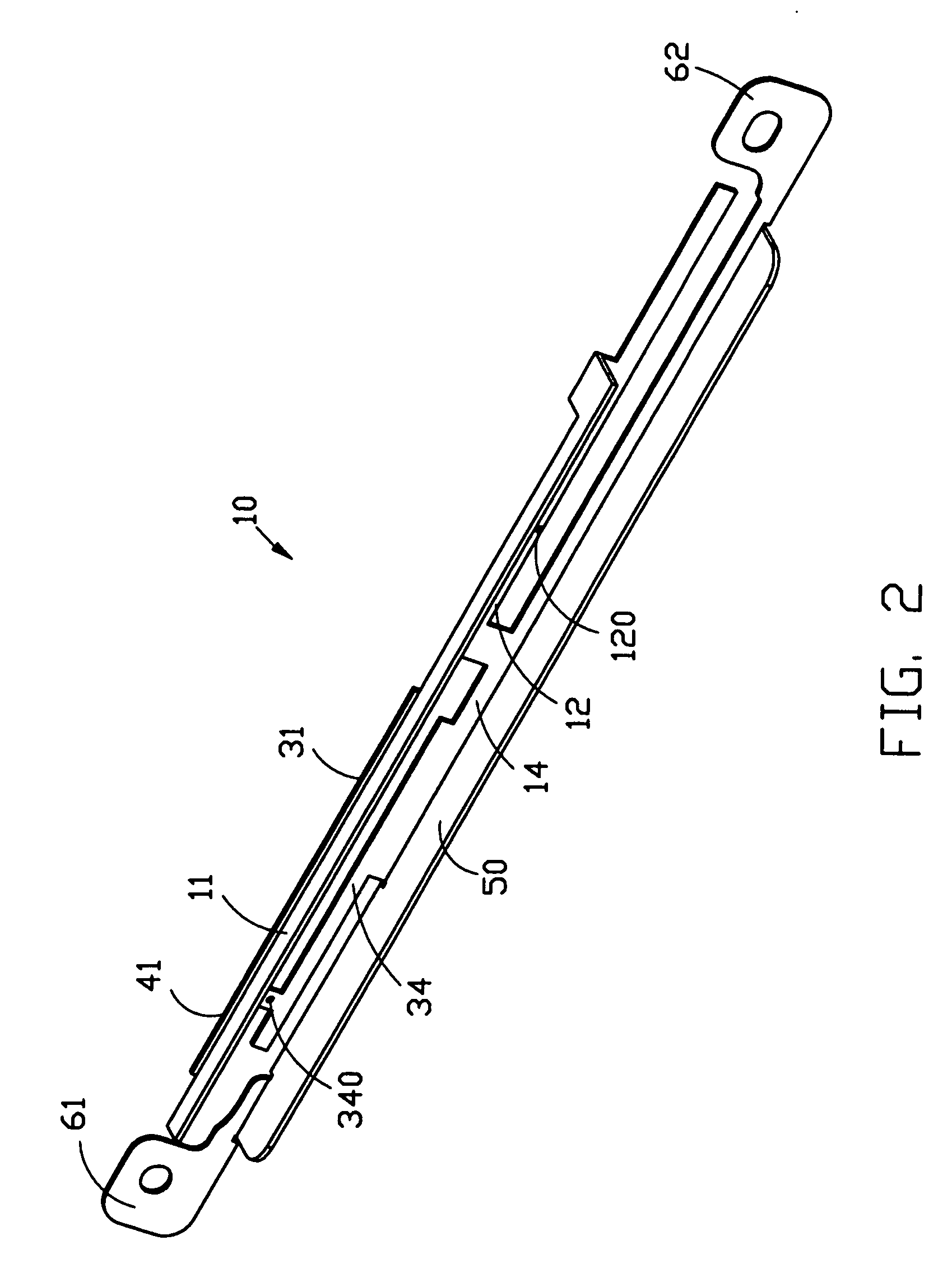
[0015] Referring to FIGS. 1 and 2, a multi-frequency antenna 10 in accordance with a preferred embodiment of the present invention comprises a first type of antenna which is used in WWAN and has first and second antennas 1, 2, and a second type of antenna which is used in WLAN and has third and fourth antenna 3, 4. The multi-frequency antenna 10 is integrally made from a metal sheet and can integrate the first type of antenna for WWAN and the second type of antenna for WLAN together.

[0016] The multi-frequency antenna 10 has a first installing portion 61 and a second installing portion 62 at opposite ends thereof, which form an installing plane. The multi-frequency antenna 10 comprises a common grounding portion 50 for the first, the second, the third and the fourth antennas 1, 2, 3, 4. A lengthwise portion 14 extends perpendicularly and upwardly from the grounding portion 50, which is ...


PUM


Abstract

A multi-frequency antenna includes a first antenna (1) and a second antenna (2) both operating at wireless wide area network, a third antenna (3) and a fourth antenna (4) both operating at wireless local area network. The first antenna, the second antenna, the third antenna and the fourth antenna are integrally made from a metal sheet and have a common grounding portion (50). The first and the second antennas have a first connecting portion (12) on which a feeding point (120) is located, and the third and the fourth antenna have a second connecting portion (34) on which another feeding point (340) is located.

Description

BACKGROUND OF THE INVENTION [0001] 1. Field of the Invention [0002] The present invention relates generally to an antenna, and more particularly to a multi-frequency antenna for a wireless communication device. [0003] 2. Description of Prior Art [0004] With the high-speed development of the mobile communication, people more and more expect to use a computer or other portable terminals to optionally connect to Internet. GPRS (General Packer Radio Service) and WLAN (Wireless Local Area Network) allow users to access data wirelessly over both cellular networks and 802.11b WLAN system. When operating in GPRS, the data transmitting speed is up to 30 Kbps˜50 Kbps, while when connected to a WLAN access point, the data transmitting speed is up to 11 Mbps. People can select different PC cards and cooperate with the portable terminals such as the notebook computer and etc. to optionally connect to Internet. Since WLAN has a higher transmitting speed, WLAN is usually used to provide public WLA...

Claims


Application Information

Patent Timeline
IPC IPC(8): H01Q1/24H01Q5/371H01Q5/40
CPCH01Q9/42H01Q5/40H01Q5/371
Inventor HUNG, CHEN-TATSENG, HSIEN-SHENGTAI, LUNG-SHENGWANG, SHU-YEAN
Owner HON HAI PRECISION IND CO LTD
Learn More