Modular converter and modular converter system

Active Publication Date: 2022-01-25
SIEMENS AG
View PDF7 Cites 0 Cited by
  • Summary
  • Abstract
  • Description
  • Claims
  • Application Information

AI Technical Summary

Benefits of technology

[0054]This advantageous embodiment of the modular converter system according to the invention makes it possible to advantageously reduce the installation space for the m

Problems solved by technology

In today's converter solutions, the solid metallic heat sink also generally assumes the function of a converter housing, either completely or as part of the converter housing, which additionally restricts flexibility in design adaptations or changes with regard to the creation of further functionality of these electrical converters due to the extensive changes which are then to be carried out, in particular with regard to their converter components.
Currently, encapsulated power modules are used for most power classes so that in terms of design, i.e. from the point of view of the space requirement and the heat balance, but also electrically, i.e. from the point of view of the inductive and ohmic connection, as central converter components, these power modules result in high development costs for each device size and a considerable outlay in production.
A problem for users is therefore that only limited possibilities exi

Method used


Image

  • Modular converter and modular converter system
  • Modular converter and modular converter system
  • Modular converter and modular converter system

Examples


Example

[0060]FIG. 1 shows a schematic representation of an electrical converter according to the prior art.

DETAILED DESCRIPTION OF PREFERRED EMBODIMENTS

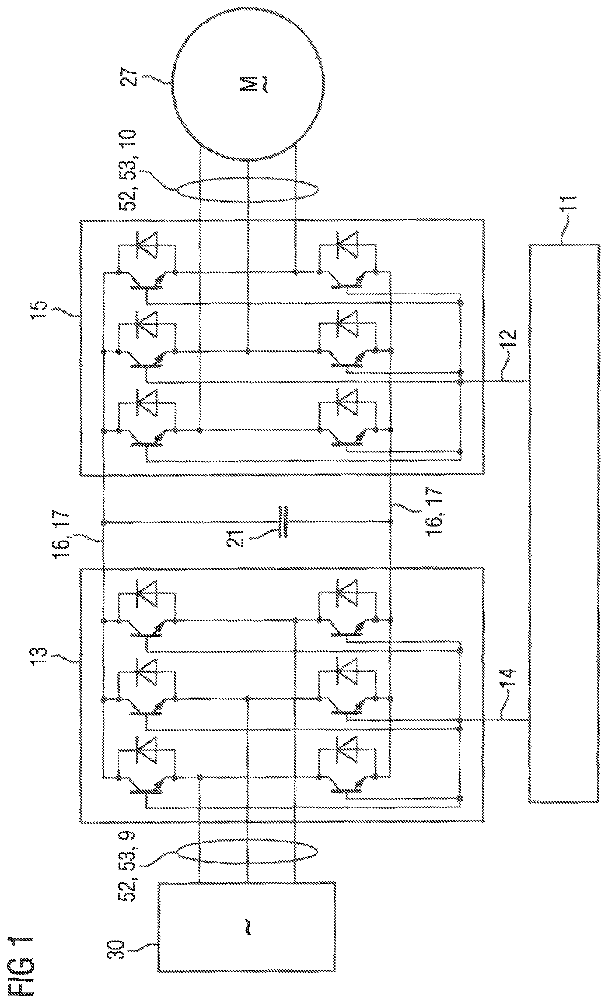
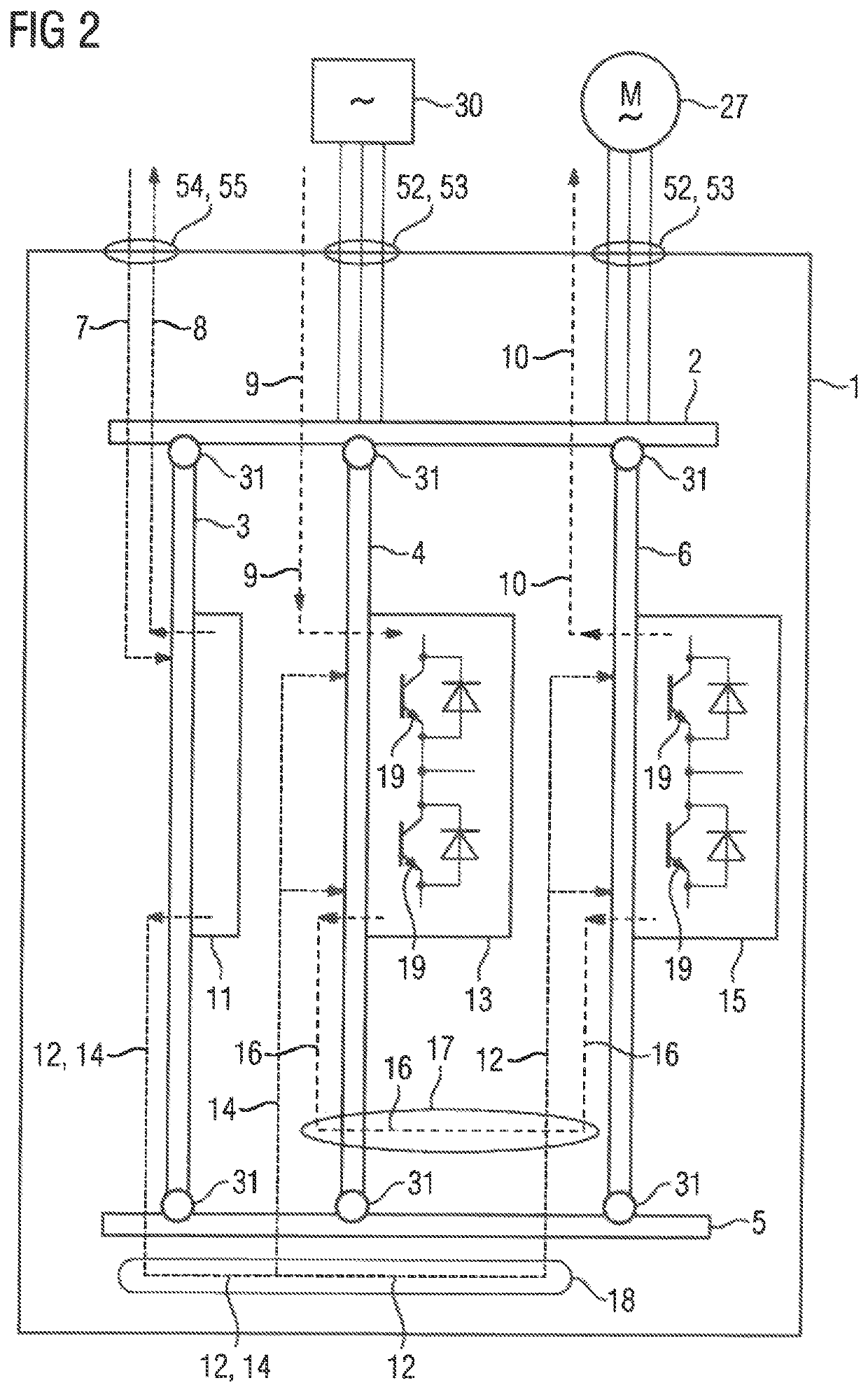
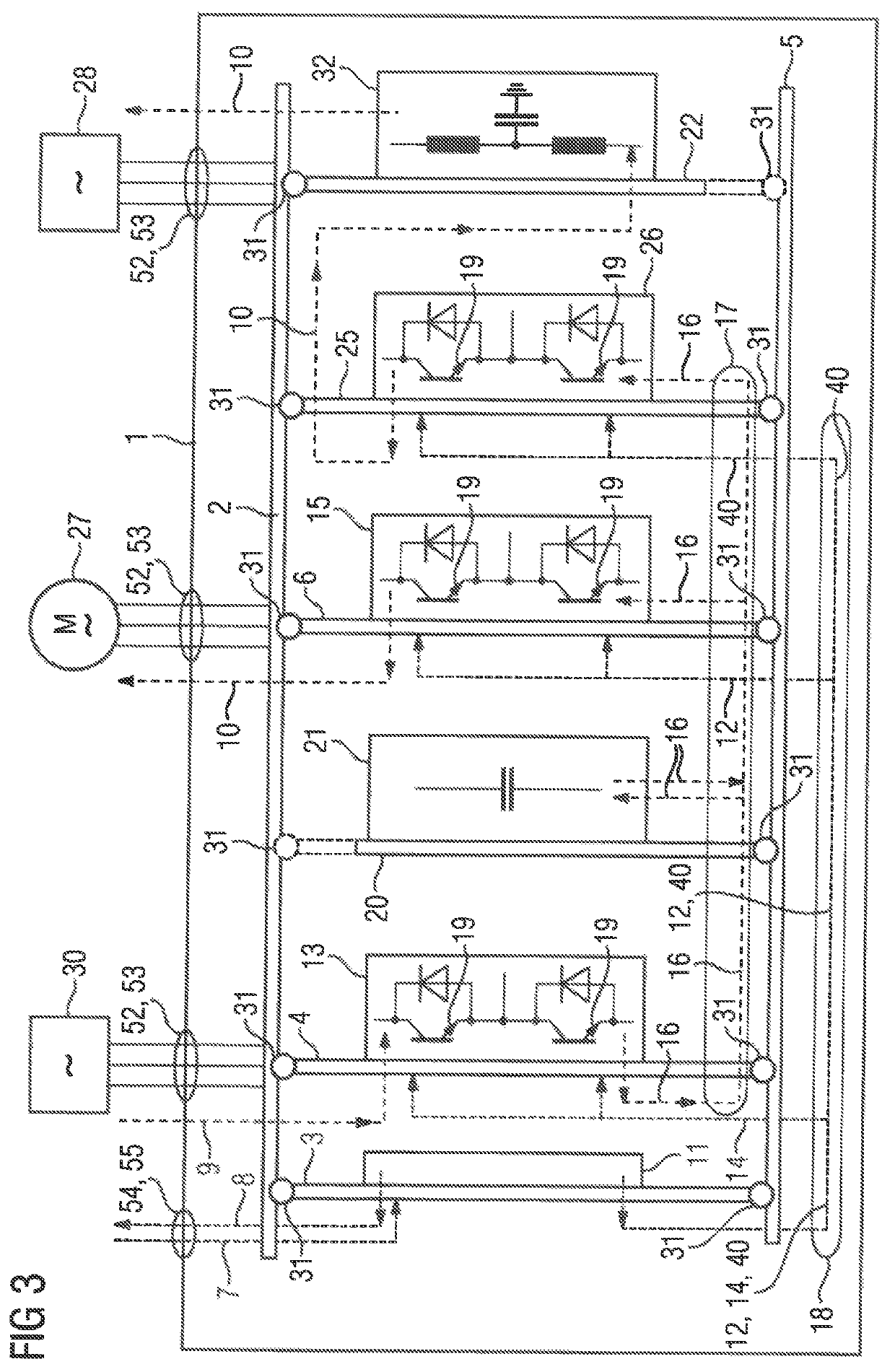
[0061]This electrical converter has, as converter components, at least one rectifier 13 with power semiconductor switches, a DC link 17 with an intermediate circuit capacitor 21, an inverter 15 with power semiconductor switches and a control unit 11 for controlling the power semiconductor switches.

[0062]A primary network 30 which in this case is connected to the rectifier 13 of the electrical converter by means of three-phase AC voltage lines 53 of a three-phase supply via AC voltage connections 52, provides an input alternating voltage 9 for operating the electrical converter during operation.

[0063]The rectifier 13 converts the three-phase input alternating voltage 9 of the primary network 30 into an intermediate circuit direct voltage 16 in the DC link 17. For this purpose, the power semiconductor switches of the rectifier 13 are switched...


PUM


Abstract

A modular converter includes an inverter having power semiconductor switches made of GaN or InGaN and being operated with a blocking voltage of at least 400V and with a clock frequency of at least 40 kHz. A connection assembly distributes input and output signals and input and output AC voltages. A control assembly generates control signals for the inverter, a supply assembly with a rectifier converts the input alternating voltage into an intermediate circuit voltage, a rear wall assembly distributes the intermediate circuit voltage and the control signals for the inverter, and a load assembly converts the intermediate circuit voltage into the output alternating voltage for a load or for a secondary network. The connection assembly and the rear wall assembly are electrically connected to the other assemblies by way of releasable mechanical connections. A modular converter system that uses the modular inverter is also described.

Description

CROSS-REFERENCES TO RELATED APPLICATIONS[0001]This application is the U.S. National Stage of International Application Na. PCT / EP 2018 / 074714, filed Sep. 13, 2018, which designated the United States and has been published as International Publication No. WO 20191063303 A1 and which claims the priority of European Patent Application, Ser. No. 17194124.8, filed Sep. 29, 2017, pursuant to 35 U.S.C. 119(a)-(d).BACKGROUND OF THE INVENTION[0002]The Invention relates to a modular converter, having a connection assembly, a control assembly, a supply assembly, a rear wall assembly and a load assembly, as well as a modular converter system with the modular converter, a rear wall bus and a converter expansion module.[0003]Electrical converters which today usually have power semiconductor switches or power modules with silicon-based power semiconductor switches arranged in bridge circuits (e.g. Si or SIC), usually require a solid metallic heat sink for heat dissipation with regard to operationa...

Claims


Application Information

Patent Timeline
IPC IPC(8): H02M7/00H02M1/44H02M5/458
CPCH02M7/003H02M1/44H02M5/4585H02M5/458Y02B70/10
Inventor FÜRST, JOHANNESDIEPOLD, FABIAN
Owner SIEMENS AG
Why Eureka
Try Eureka