Liquid Feeding Type Screw Compressor

Active Publication Date: 2018-04-19
HITACHI IND EQUIP SYST CO LTD
View PDF3 Cites 0 Cited by
  • Summary
  • Abstract
  • Description
  • Claims
  • Application Information

AI Technical Summary

Benefits of technology

[0009]According to an aspect of the present invention, it is possible to reduce the installation space for the liquid feeding type screw compressor, and to improve the vibration insulat

Problems solved by technology

In such a distributed arrangement, the installation space for the individual compr

Method used


Image

  • Liquid Feeding Type Screw Compressor
  • Liquid Feeding Type Screw Compressor
  • Liquid Feeding Type Screw Compressor

Examples


Example

Embodiment 1

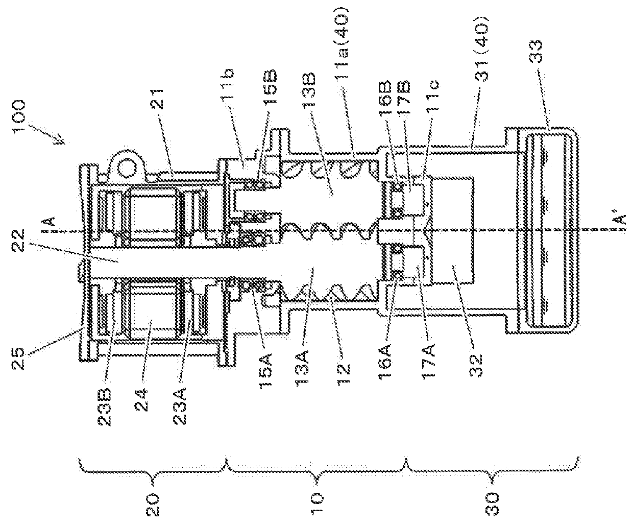
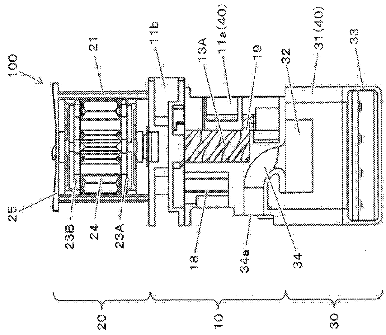
[0032]FIG. 1 is a longitudinal sectional view as seen from the front side of an oil cooled type screw compressor according to Embodiment 1 of the present invention, and FIG. 2 is a side longitudinal sectional view taken along line A-A′ of FIG. 1. In an oil cooled type screw compressor, oil is supplied to a compression operation chamber in order to cool the compressed air, to lubricate screw rotors, and to seal a gap between the screw rotors and a gap in the compression operation chamber. The present invention is also applicable to a case where water or the like is supplied instead of oil.

[0033]An oil cooled type screw compressor 100 includes, as components, a compressor main body 10, a motor 20 driving the compressor main body 10, and an oil separator 30 as a gas-liquid separator primarily separating the oil from the compressed air discharged from the compressor main body 10. The motor 20 is arranged above the compressor main body 10 such that a shaft 22 of the motor 20 ...

Example

Embodiment 2

[0048]FIG. 4 is a longitudinal sectional view as seen from the front side of an oil cooled type screw compressor according to Embodiment 2 of the present invention. As compared with the oil cooled type screw compressor 100 according to Embodiment 1 (see FIG. 1), the oil cooled type screw compressor 101 according to the present embodiment differs in that it is equipped with an integral type casing 41 as a single member obtained by integrally molding a motor casing 21 and a suction side casing 11b.

[0049]In the oil cooled type screw compressor 101 according to the present embodiment, it is possible to attain the same effects as those of the oil cooled type screw compressor 100 according to Embodiment 1 (see FIG. 1), and there is provided the integral type casing 41 obtained by integrally molding the motor casing 21 constituting the contour of the motor 20 and the suction side casing 11b constituting the contour of the compressor main body 10, whereby the casing rigidity of...

Example

Embodiment 3

[0051]FIG. 5 is a longitudinal sectional view as seen from the front side of an oil cooled type screw compressor according to Embodiment 3 of the present invention. The oil cooled type screw compressor 102 according to the present embodiment is equipped with an integral type casing 42 as a single member obtained by integrally molding the motor casing 21, the suction side casing 11b, and the compressor main body casing 11a. The integral type casing 42 and the outer cylinder casing 31 of the oil separator 30 are connected together airtightly with a flange or the like.

[0052]In the oil cooled type screw compressor 102 according to the present embodiment, due to the integral molding of the suction side casing 11b and the compressor main body casing 11a, the rotors 13A and 13B cannot be accommodated in the rotor accommodating chamber 12 from the suction side of the compressor main body 10. In view of this, in order that the male rotor 13A and the female rotor 13B can be accomm...


PUM


Abstract

There is provided a liquid feeding type screw compressor that can reduce size and weight and improve vibration insulation and sound insulation. A liquid feeding type screw compressor includes as components: a compressor main body; a motor driving the compressor main body; and a gas-liquid separator separating a liquid from a compressed air discharged from the compressor main body. The motor is arranged above the compressor main body. The gas-liquid separator is arranged below the compressor main body. A compressor main body casing constituting an inner cylindrical space forming a compression operation chamber together with the screw rotor and constituting the contour of the compressor main body and a casing constituting the contour of another component consist of an integrally molded single member.

Description

TECHNICAL FIELD[0001]The present invention relates to a liquid feeding type screw compressor supplying a liquid into a compression chamber when, for example, cooling compression heat generated in a compressor main body.BACKGROUND ART[0002]In recent years, in plants, distributed arrangement of compressors are being promoted, with compressors for various uses being arranged at various locations in the vicinity of the production line. In such a distributed arrangement, the installation space for the individual compressors is limited, so that there is a demand for space saving for the compressors.[0003]Patent Document 1 discloses an example of a technique for reducing the installation space for a compressor. In a rotary compressor system 10 (an oil cooled type screw compressor) shown in FIG. 3 of Patent Document 1, a compressor unit 11 (a compressor main body) is arranged above a pressure container 14 (an oil separator), and besides, a motor 12 is arranged above the compressor unit 11 (...

Claims


Application Information

Patent Timeline
IPC IPC(8): F04C29/02F04C18/16
CPCF04C29/026F04C18/16F04C2240/30F04C2240/20F01C21/10F04C2230/21
Inventor SADAKATA, KOSUKENISHIMURA, HITOSHIHARASHIMA, TOSHIKAZUYAMAMOTO, KENTAROTSUCHIYA, TAKESHICHIBA, KOTARO
Owner HITACHI IND EQUIP SYST CO LTD
Why Eureka
Try Eureka