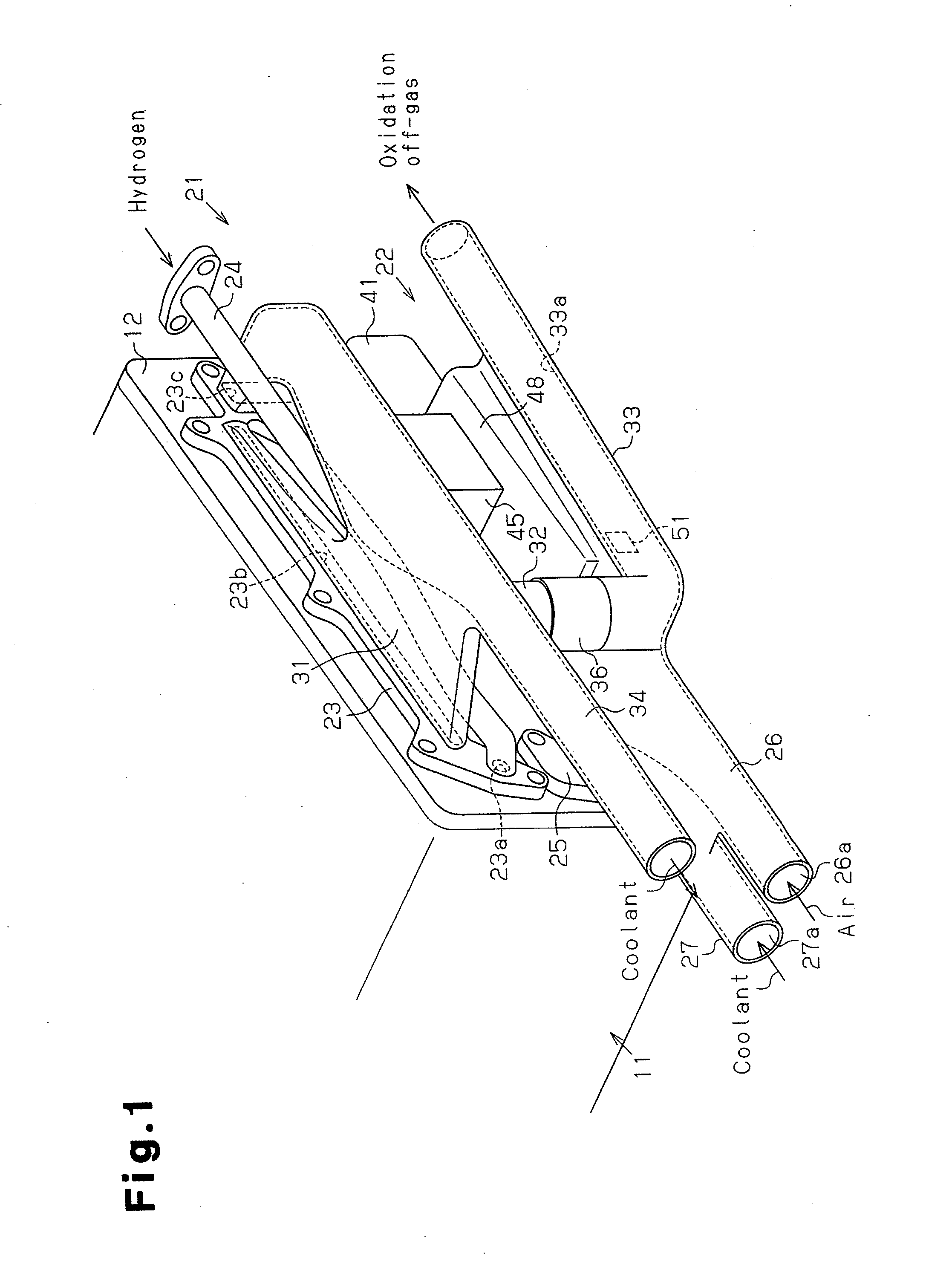
[0023]A fuel cell system for an automobile according to one embodiment of the present invention will now be described with reference to FIGS. 1 to 13.
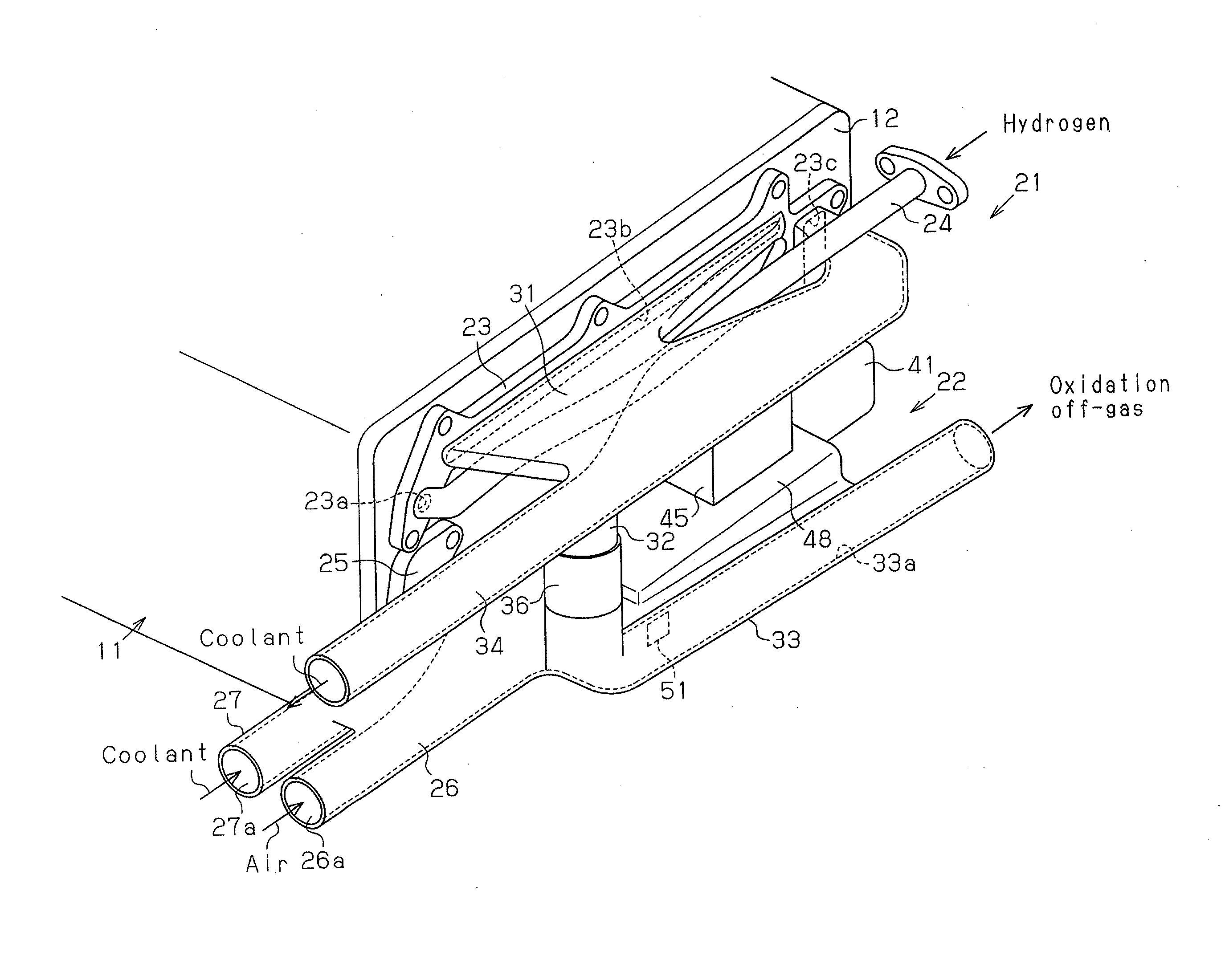
[0024]As shown in FIG. 1, the fuel cell system includes a fuel cell stack 11. The fuel cell stack 11 has laminated power generating cells (not shown). Hydrogen gas as fuel gas is supplied to the fuel electrode of each power generating cell. Air (oxygen gas) as oxidation gas is supplied to the oxidant electrode. As a result, through the electrochemical reactions between hydrogen gas and oxygen, electric energy is extracted and the water is generated.
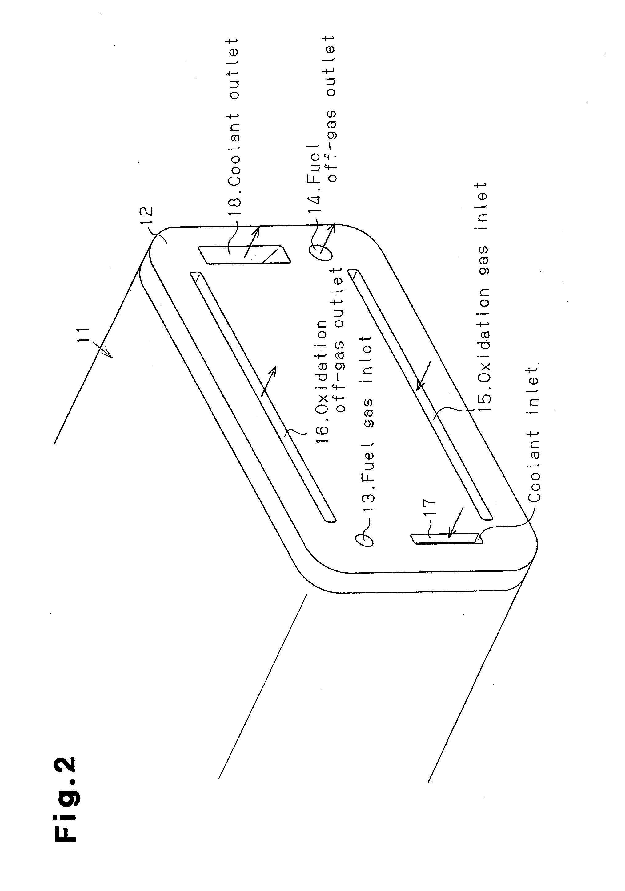
[0025]As shown in FIG. 2, an end plate 12 made of an insulation material is fixed to an end face of the fuel cell stack 11 with bolts (not shown). A fuel gas inlet 13 is formed in a left upper part of the end plate 12. A fuel off-gas outlet 14 is formed in a right lower part of the end plate 12. A laterally extending oxidation gas inlet 15 is formed in a lower part of the end plate 12. A laterally extending oxidation off-gas outlet 16 is formed in an upper part of the end plate 12. A coolant inlet 17 is formed in a left lower part of the end plate 12. The coolant inlet 17 communicates with a cooling jacket formed in the fuel cell stack 11. A coolant outlet 18 is formed in a right upper part of the end plate 12.
[0026]As shown in FIGS. 1 and 4, first and second piping units 21, 22 are detachably fixed to the end plate 12 with bolts (not shown). As shown in FIG. 5, the first and second piping units 21, 22 are separate bodies. The first piping unit 21 has a first attachment base 23, to which a fuel gas supply pipe 24, a first oxidation off-gas discharge pipe 31, and a coolant discharge pipe 34 are integrated. Most of the fuel gas supply pipe 24 is arranged to pass through between the end plate 12 and the coolant discharge pipe 34. The second piping unit 22 has a second attachment base 25, to which an oxidation gas supply pipe 26, a coolant supply pipe 27, a second oxidation off-gas discharge pipe 33, a hydrogen separator 41, and a diluter 48 are integrated. A joint 36 and a pump 45 are arranged between the first piping unit 21 and the second piping unit 22.
[0027]As shown in FIG. 3, the first attachment base 23 has an inlet hole 23a communicating with the fuel gas inlet 13 of the end plate 12, an outlet hole 23b communicating with the oxidation off-gas outlet 16, and an outlet hole 23c communicating with the coolant outlet 18. As shown in FIG. 1, the distal end of the fuel gas supply pipe 24 is integrally coupled to the first attachment base 23 so as to communicate with the inlet hole 23a, that is, with the fuel gas inlet 13. Fuel gas is therefore supplied to the fuel electrodes in the fuel cell stack 11 through the fuel gas supply pipe 24.
[0028]As shown in FIGS. 1, 3, and 6, the first oxidation off-gas discharge pipe 31, which is formed to have a flat shape, is integrally coupled to the first attachment base 23 so as to communicate with the outlet hole 23b, that is, the oxidation off-gas outlet 16. As shown in FIG. 10, a discharge cylinder 32 projects downward from the bottom wall of the first oxidation off-gas discharge pipe 31. The coolant discharge pipe 34 is integrally coupled to the first oxidation off-gas discharge pipe 31 so as to communicate with the outlet hole 23c of the first attachment base 23, that is, with the coolant outlet 18. An oxidation off-gas discharge passage 31a of the oxidation off-gas discharge pipe 31 and a coolant discharge passage 34a of the coolant discharge pipe 34 are separated from each other by a single partition wall 35.
[0029]The second attachment base 25 has an inlet hole 25a communicating with the oxidation gas inlet 15 of the end plate 12, an inlet hole 25b communicating with the coolant inlet 17, and an outlet hole 25c communicating with the fuel off-gas outlet 14. As shown in FIGS. 7 and 8, the distal end of the oxidation gas supply pipe 26 is integrally coupled to the second attachment base 25 so as to communicate with the inlet hole 25a, that is, with the oxidation gas inlet 15. The distal end of the coolant supply pipe 27 is coupled to the second attachment base 25 so as to communicate with the inlet hole 25b, that is, with the coolant inlet 17. As shown in FIG. 7, the oxidation gas supply pipe 26 and the coolant supply pipe 27 are formed integrally. An oxidation gas supply passage 26a of the oxidation gas supply pipe 26 and a coolant supply passage 27a of the coolant supply pipe 27 are separated from each other by a single partition wall 28.
[0030]As shown in FIGS. 1 and 8, the second oxidation off-gas discharge pipe 33 is coupled to the outer side surface of the oxidation gas supply pipe 26. As shown in FIG. 10, one end of the discharge pipe 33 projects upward. The joint 36 couples the discharge cylinder 32 and the projecting ends of the second oxidation off-gas discharge pipe 33 to each other.
[0031]As shown in FIGS. 7 and 8, the hydrogen separator 41 is formed integrally with the second attachment base 25 to communicate with the second outlet hole 25c, that is, with the fuel off-gas outlet 14. A separation chamber 43 is defined in the hydrogen separator 41. A structure for separating hydrogen from fuel off-gas (not shown) is provided in the separation chamber 43. As shown in FIG. 4, the pump 45 (see FIG. 5) is connected to a hydrogen gas outlet 44 of the separation chamber 43. The discharge port (not shown) of the pump 45 is connected to a middle part (see FIG. 11) of the fuel gas supply pipe 24 via a pipe 46. As shown in FIGS. 8 and 12, the diluter 48 is formed integrally with the hydrogen separator 41. The diluter 48 is arranged adjacent to a fuel off-gas outlet 47 of the separation chamber 43. The diluter 48 has a dilution chamber 49, in which a plurality of meandering plates 50 in which the plates are alternately arranged. The communication hole 51 is formed at the downstream side of the dilution chamber 49. The dilution chamber 49 communicates with the second oxidation off-gas discharge passage 33a of the discharge pipe 33 through the communication hole 51.
[0032]As shown in FIG. 8, the oxidation gas supply pipe 26, the discharge pipe 33, and the diluter 48 are formed integrally. The oxidation gas supply passage 26a of the oxidation gas supply pipe 26 and the dilution chamber 49 of the diluter 48 are separated from each other by a single partition wall 52. Also, the second oxidation off-gas discharge passage 33a and the dilution chamber 49 are separated from each other by a single partition wall 53. In the present embodiment, the hydrogen separator 41 and the diluter 48 function as a fuel off-gas pipe connected to the outlet hole 25c of the second attachment base 25 (the fuel off-gas outlet 14).
[0033]The first and second piping units 21, 22 are each preferably formed as an integral body except for the pump 45 and the pipe 46. Since it is difficult to integrally mold the fuel gas supply pipe 24, the fuel gas supply pipe 24 may be molded separately and then connected to the piping unit. In addition, the hydrogen separator 41 and the diluter 48 are molded separately, and coupled to the piping units.
[0034]The operation of the above described fuel cell system will now be described.
[0035]With reference to FIGS. 1 and 4, hydrogen gas is supplied to the supply pipe 24 from a hydrogen gas tank (not shown). The hydrogen gas is supplied to the anode-side fuel electrode of the fuel cell stack 11 through the inlet hole 23a of the first attachment base 23 and the fuel gas inlet 13 of the end plate 12. On the other hand, air is supplied to the oxidation gas supply passage 26a of the oxidation gas supply pipe 26 from a compressor (not shown). The air is supplied to the cathode-side oxidant electrode of the fuel cell stack 11 through the inlet hole 25a of the second attachment base 25 and the oxidation gas inlet 15 of the end plate 12. Further, coolant is supplied to the coolant supply passage 27a of the coolant supply pipe 27 by a pump (not shown). The coolant is supplied to the cooling jacket of the fuel cell stack 11 through the inlet hole 25b of the second attachment base 25 and the coolant inlet 17 of the end plate 12. In the fuel cell stack 11, the hydrogen gas supplied to the fuel electrode and the oxygen in the air supplied to the oxidant electrode are electrochemically reacted with each other to generate electricity. The electricity is then supplied, for example, to a drive motor of the automobile through electrode terminals.
[0036]The hydrogen gas that has been used for generating electricity becomes fuel off-gas and is supplied to the separation chamber 43 through the fuel off-gas outlet 14 of the end plate 12 and the outlet hole 25c of the second attachment base 25 shown in FIG. 13. In the separation chamber 43, fuel gas is separated from the fuel off-gas. The separated fuel gas is supplied to the fuel gas supply pipe 24 through the pipe 46 by the pump 45 shown in FIG. 4, so as to be reused. The fuel off-gas, from which most of fuel gas has been separated in the separation chamber 43, is introduced into the dilution chamber 49 of the diluter 48 through the outlet 47 shown in FIG. 8. While the fuel off-gas flows in the dilution chamber 49 along the meandering plates 50, hydrogen gas contained in the fuel off-gas is diluted. The diluted fuel-off gas flows into the second oxidation off-gas discharge passage 33a of the discharge pipe 33 from the communication hole 51. The fuel off-gas is further diluted with oxidation off-gas flowing through the second oxidation off-gas discharge passage 33a, and is then discharged to the outside from the discharge pipe 33.
[0037]In the cooling jacket in the fuel cell stack 11, the coolant that has been used for reducing the heat caused by the generation of electricity is discharged into the coolant discharge passage 34a in the coolant discharge pipe 34, through the coolant outlet 18 of the end plate 12 and the outlet hole 23c of the attachment base 23 shown in FIG. 6. The coolant is again drawn to the heat exchanger by a circulation pump (not shown). After being cooled by the heat exchanger, the coolant is supplied to the coolant supply passage 27a of the coolant supply pipe 27.
[0038]The advantages of the above described fuel cell system will now be described.
[0039](1) As shown in FIG. 7, the oxidation gas supply pipe 26 and the coolant supply pipe 27 are integrated, and the oxidation gas supply passage 26a and the coolant supply passage 27a are separated from each other by the single partition wall 28. This structure allows air in the oxidation gas supply passage 26a, which air has been heated through adiabatic compression by the compressor, to be effectively cooled by the low temperature coolant flowing through the coolant supply passage 27a. This improves the power generation efficiency in the fuel cell stack 11. Further, since there is no clearance between the oxidation gas supply pipe 26 and the coolant supply pipe 27, the installation space for the pipes 26, 27 is reduced. This reduces the weight and size of the second piping unit 22.
[0040](2) As shown in FIG. 6, the first oxidation off-gas discharge pipe 31 and the coolant discharge pipe 34 are integrated, and the oxidation off-gas discharge passage 31a and the coolant discharge passage 34a are separated from each other by the single partition wall 35. This structure reduces the installation space of the oxidation off-gas discharge pipe 31 and the coolant discharge pipe 34, thereby reducing the weight and size of the first piping unit 21.
[0041](3) As shown in FIG. 8, the oxidation gas supply pipe 26, the discharge pipe 33, and the diluter 48 are integrated, the oxidation gas supply passage 26a and the dilution chamber 49 are separated from each other by the single partition wall 52, and the second oxidation off-gas discharge passage 33a and the dilution chamber 49 are separated from each other by the single partition wall 53. This structure reduces the installation space of the oxidation gas supply pipe 26, the discharge pipe 33, and the diluter 48, thereby reducing the weight and size of the oxidation gas supply pipe 26, the discharge pipe 33, and the diluter 48.
[0042]The above described embodiment may be modified as follows.
[0043]As shown in FIG. 14, the housing of the pump 45 may be surrounded by the coolant supply pipe 27, so that the outer circumferential surface of the coolant supply pipe 27 contacts the outer surface of the housing of the pump 45. This allows the pump 45 to be cooled by coolant flowing through the coolant supply passage 27a. Cooling of the pump 45 cools hydrogen gas supplied from the pipe 46 to the fuel gas supply pipe 24 by the pump 45 to an appropriate temperature. The power generation efficiency is thus improved.
[0044]The first piping unit 21 and the second piping unit 22 may be formed integrally.