

Power-station installation
a power-station and installation technology, applied in the direction of substations, non-enclosed substations, electrical storage systems, etc., can solve the problems of large physical complexity, capital and resource-intensive, and little design flexibility for installation
- Summary
- Abstract
- Description
- Claims
- Application Information
AI Technical Summary
Benefits of technology
Problems solved by technology
Method used
Image

Examples
Embodiment Construction
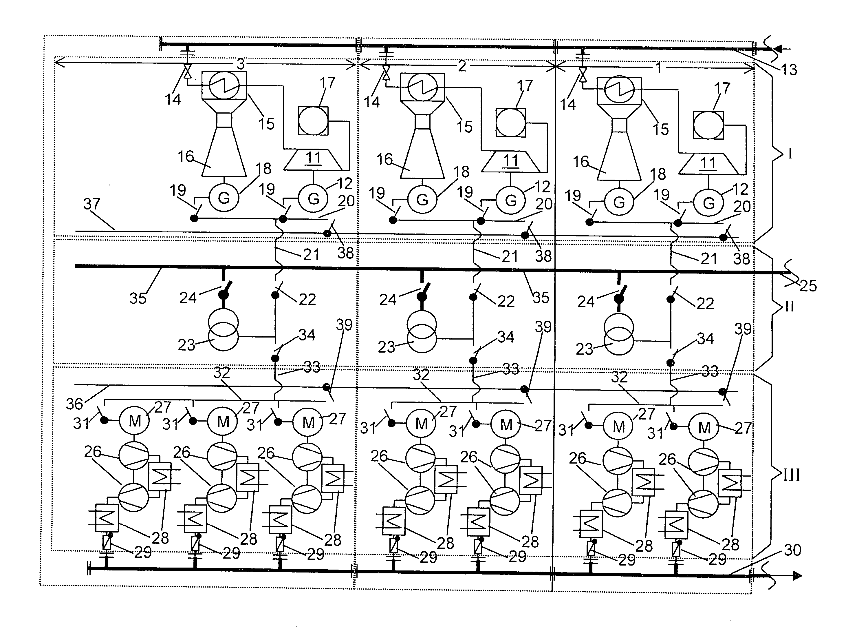
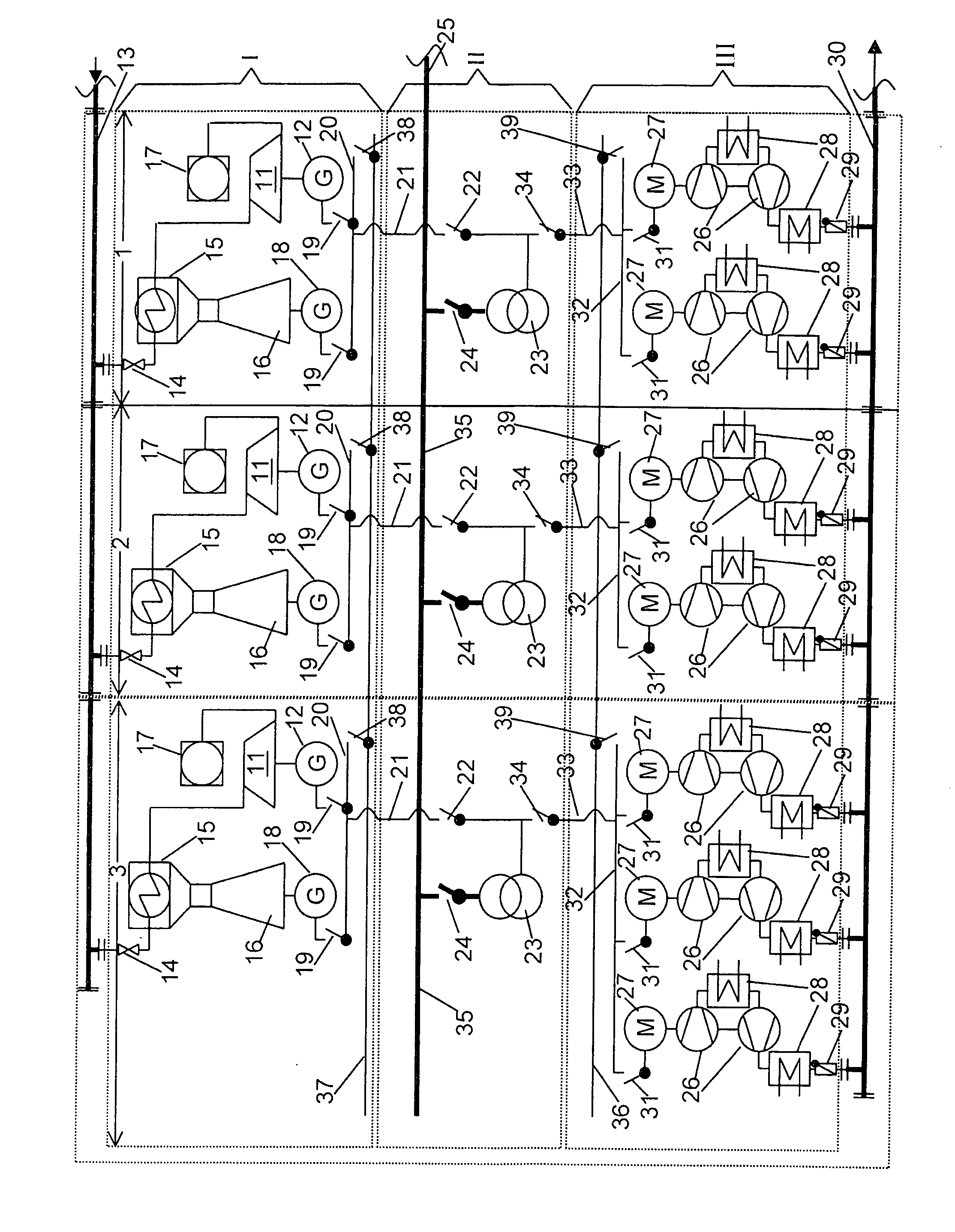
[0006] The invention provides a remedy for this. The invention as characterized in the claims is based on the object of specifying a power-station installation of the type mentioned initially which has the capability to avoid the disadvantages of the prior art, with one particular aim being to increase the availability of the compressed-air energy storage power-station installation. A further aim is to improve the flexibility for planning, for the construction and extension phase, for maintenance and for operation, thus resulting in significantly increased availability and thus use of all the invested resources. A further aim of the invention is to minimize the use of resources without having to accept functional restrictions.
[0007] According to a first aspect of the invention, this object is achieved using the totality of the features of claim 1. According to a second aspect of the invention, this object is achieved using the totality of the features of claim 2.
[0008] The essence...
PUM
 Abstract
Description
Claims
Application Information