Modular light emitting diode

a light-emitting diode and module technology, applied in the field of modules, can solve the problems of easy damage to the packaging chip, waste of time and manpower, and complicated detachment of the damaged light-emitting diode from the circuit board, and achieve the effects of good waterproofing, rapid heat sinking, and flexible assembly

Inactive Publication Date: 2006-11-23
PARA LIGHT ELECTRONICS
View PDF4 Cites 118 Cited by
  • Summary
  • Abstract
  • Description
  • Claims
  • Application Information

AI Technical Summary

Benefits of technology

[0005] It is a main object of the present invention to provide a modular light emitting diode having the advantages of good waterproofing, rapid heat sinking, and flexible assembly.
[0006] In order to achieve the aforementioned object, a modular light emitting diode is disclosed. The modular light emitting diode comprises a heat-sinking base, a circuit board, a LED light emitting device, and a waterproofing layer. A protrudent portion and a plurality of trenches are formed on the surface of the heat-sinking base. Waterproof connection terminals are mounted on both sides of the circuit board. The LED light emitting device is mounted on and connected to the circuit board so as to form a complete circuit. Thereafter, the circuit board on which the LED light emitting device is mounted is stacked on the heat-sinking base to allow the LED light emitting device to be mounted on the protrudent portion of the heat-sinking base. These three stacked components are locally packaged by a waterproofing layer to complete the modular light emitting diode having the advantages of good waterproofing, rapid heat sinking, and flexible assembly.

Problems solved by technology

Accordingly, the packaged chip is easily damaged by the heat stress.
Moreover, the major deficiency of the conventional structure consists in that it is very complicated to detach the damaged light emitting diode from the circuit board to replace it with a new one when the light emitting diode is damaged.
Consequently, a lot of time and manpower are wasted.

Method used


Image

  • Modular light emitting diode
  • Modular light emitting diode
  • Modular light emitting diode

Examples


Embodiment Construction

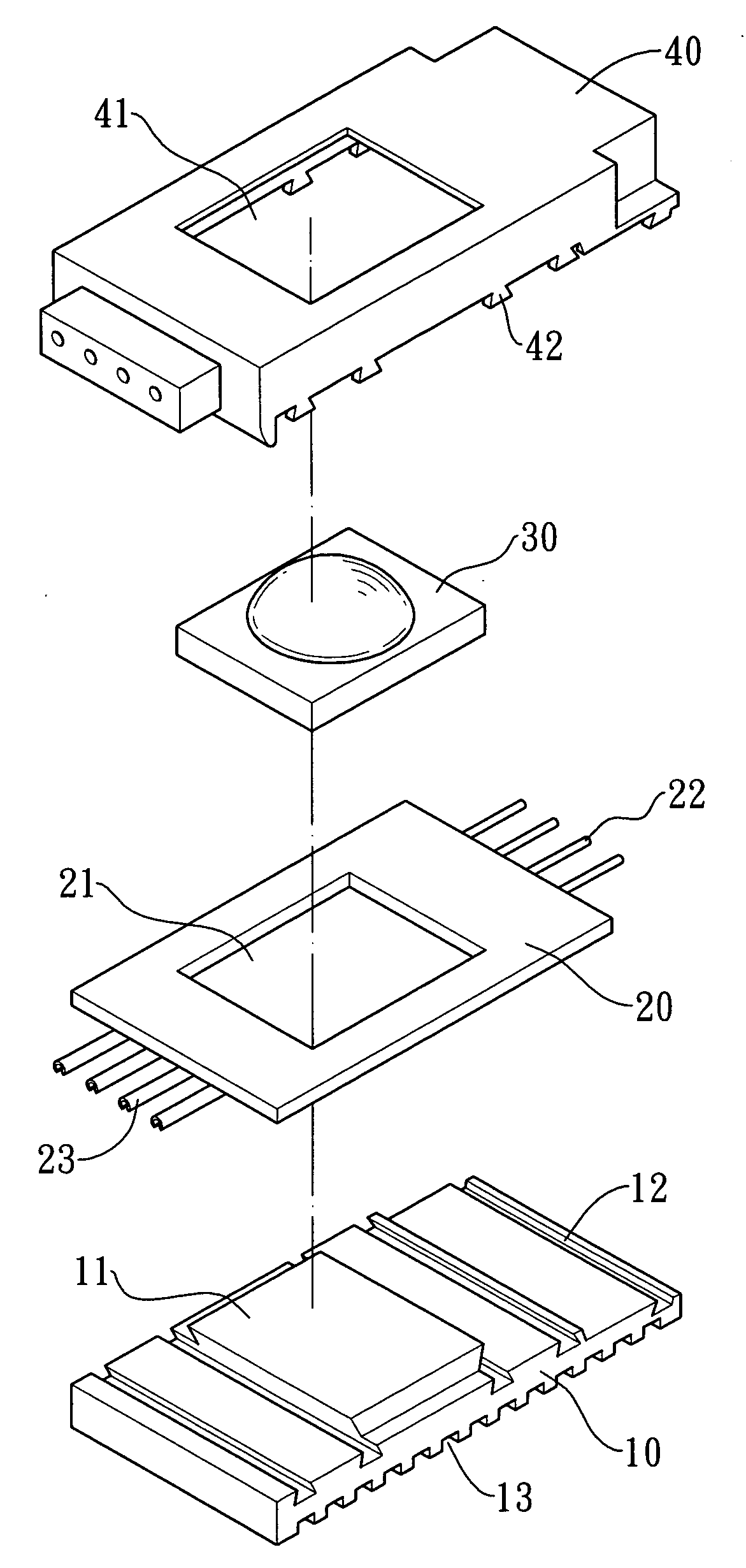
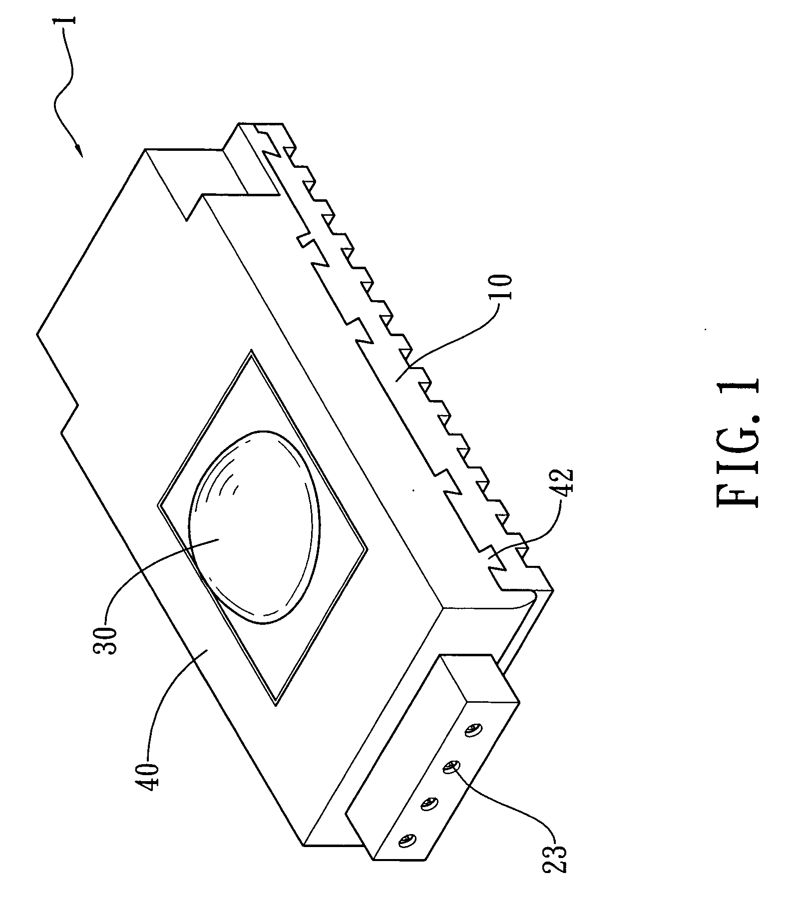
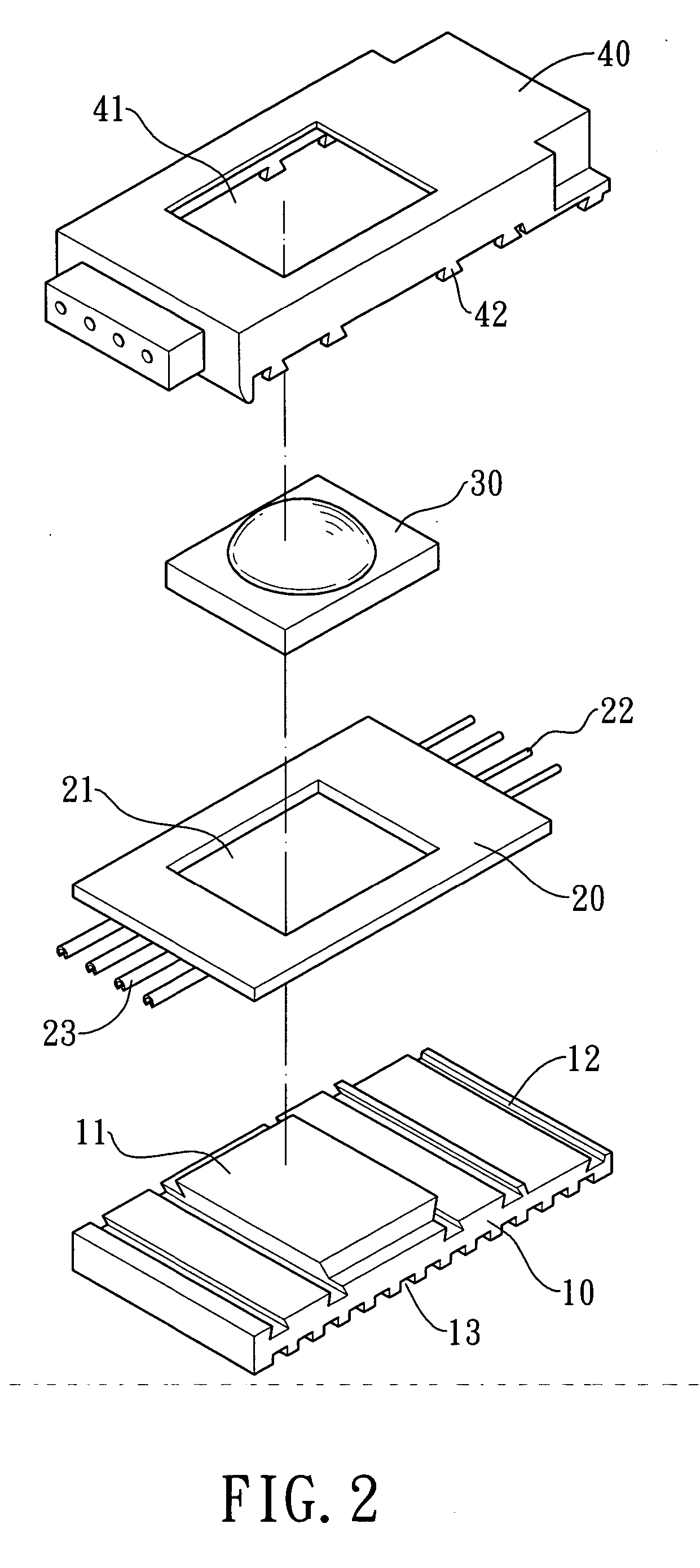
[0013] Referring to FIG. 1 and FIG. 2, a modular light emitting diode 1 of the present invention comprises: a heat-sinking base 10, an circuit board 20, a LED light emitting device 30, and a waterproofing layer 40, wherein a large-area protrudent portion 11 and several trenches 12 are formed on the surface of the heat-sinking base 10. Besides, several trenches 13 are formed on the bottom surface of the heat-sinking base 10 to increase the surface area for heat sinking.

[0014] A hole 21 is formed on the circuit board 20 corresponding to the protrudent portion 11 of the heat-sinking base 10, and different circuits may be designed to be formed on the circuit board 20 in accordance with different needs. Besides, waterproof (male and female) connection terminals 22, 23 are mounted on the opposite sides of the circuit board 20. Moreover, the connection terminals 22, 23 are inwardly extended into the hole 21 to form at least two contacts (not shown) around the hole 21.

[0015] The LED light...


PUM


Abstract

A modular light emitting diode is disclosed. The modular light emitting diode comprises a heat-sinking base, a circuit board, a LED light emitting device, and a waterproofing layer. A protrudent portion and a plurality of trenches are formed on the surface of the heat-sinking base. Waterproof connection terminals are mounted on both sides of the circuit board. The LED light emitting device is mounted on and connected to the circuit board so as to form a complete circuit. Thereafter, the circuit board on which the LED light emitting device is mounted is stacked on the heat-sinking base to allow the LED light emitting device to be mounted on the protrudent portion of the heat-sinking base. These three stacked components are locally packaged by a waterproofing layer to complete the modular light emitting diode having the advantages of good waterproofing, rapid heat sinking, and flexible assembly.

Description

FIELD OF THE INVENTION [0001] The present invention relates to a modular light emitting diode having the advantages of good waterproofing, rapid heat sinking, and flexible assembly for being suitable for a photoelectric package, for example, a light emitting diode or the like. BACKGROUND OF THE INVENTION [0002] Because of having low power consumption and long lifetime, the light emitting diode is widely applied to various light emitting structures such as traffic lights, emergency illumination, emergency signs, etc. The conventional light emitting diode is shown in FIG. 5. A chip B is mounted in a notched cup A1 (optical cavity) of a first frame A, and connected to a second frame D via a metal wire C. The top ends of the first frame A and the second frame D, the chip B, and the metal wire C are packaged by a transparent layer E to complete the manufacture of the light emitting diode. [0003] The required amount of light emitting diodes must be welded to the circuit board first before...

Claims


Application Information

Patent Timeline
Patent Type & Authority Applications(United States)
IPC IPC(8): F21V21/00
CPCF21S2/005F21V29/763F21V21/005F21V23/06F21V29/004F21W2111/02F21Y2101/02H01L33/642F21V31/04F21S4/008H01L2224/48091H01L2224/48247H01L2224/73265F21S4/001H01L2924/00014F21S4/10F21S4/28F21Y2115/10F21V23/006F21V23/005F21V29/70
Inventor LIN, HUEI-TSOLIN, CHING-YUAN
Owner PARA LIGHT ELECTRONICS
Why Eureka
Try Eureka