Display device and method of displaying data thereon

a technology of display device and data display, which is applied in the direction of instruments, lighting and heating equipment, transportation and packaging, etc., can solve the problems of complex optical system, voluminous, inflexible, expensive and/or difficult implementation, etc., and achieve the effect of simple and cheap optical system

Active Publication Date: 2006-11-23
LEIA INC +1
View PDF6 Cites 68 Cited by
  • Summary
  • Abstract
  • Description
  • Claims
  • Application Information

AI Technical Summary

Benefits of technology

[0005] It is an object of the invention to provide a display device having a relatively simple and cheap optical system.
[0013] The invention provides a display device which is suitable for generating directional images. The display device may be flexible, easy to implement and / or have a low volume. Specifically, the invention provides a display device which has an integrated optical system and may be suitable for mobile use.
[0016] The display device may further comprise means for alternating between illumination of the first and second light sources and means for alternating between displaying a first and a second image on the display panel substantially synchronously with alternating between illumination of the first and second light sources. The display device may be capable of switching between the first and the second image, so fast that it is not perceivable by a user, i.e. so fast that a user does not perceive any flickering due to the switching between the first and the second image. This may provide a display device on which different images may be sent to a user, e.g. different images may be sent to the left and the right eye of a user. Furthermore, this allows use of a single display device by more than one user.
[0017] The display device may comprise an optical system having a first and a second groove structure arranged in an opposed configuration. This may be a robust and flexible way of arranging the first and second groove structures because no additional components may be necessary for directing the light between the two groove structures.

Problems solved by technology

Such a display device and other display devices of the prior art comprise complex optical systems, are voluminous, inflexible, expensive and / or difficult to implement.

Method used


Image

  • Display device and method of displaying data thereon
  • Display device and method of displaying data thereon
  • Display device and method of displaying data thereon

Examples


Embodiment Construction

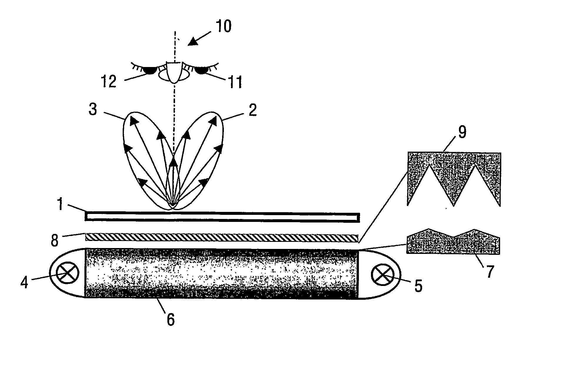
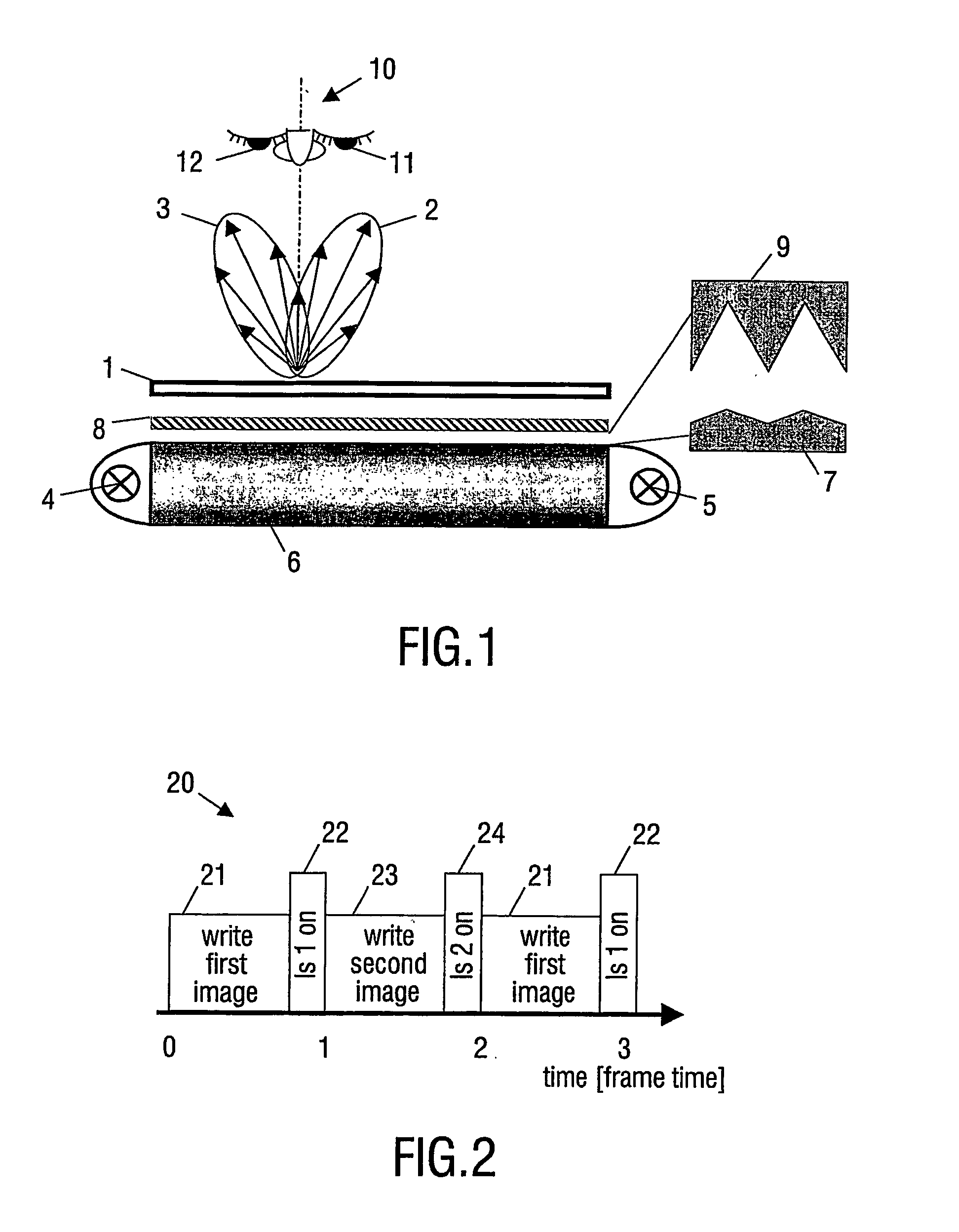
[0042]FIG. 1 is a schematic cross-sectional view of a display device in accordance with a preferred embodiment of the invention. An LCD display 1 is used as a display panel. Light 2, 3 is emitted from light sources 4, 5, e.g. cold cathode fluorescent lamps or light-emitting diodes. The light emitted from the first light source 4 is directed through the display panel 1 with a first angular distribution 2, i.e. in a first light cone, and the light from the second light source 5 is directed through the display panel 1 with a second angular distribution 3, i.e. in a second light cone. Light emitted from the light sources 4, 5 is guided from the light sources by a light guide 6, which has an out-coupling surface with a second groove structure 7. The light, which is coupled out of the light guide 6, is coupled into a light redirection element 8. The light redirection element 8 has an in-coupling surface with a first groove structure 9. The light guide 6 and the light redirection element 8...


PUM


Abstract

The invention relates to a display device with directional backlight. Stereoscopic images are produced by emitting light in two restricted and limited angular cones. Light is alternatively sent to the left and to the right eye of the observer synchronously with switching between images for the left and the right eye on a fast switching LCD. Alternatively, images may be produced for two or more observers and directed towards a multitude of directions. The display device comprises: a display panel (1), a light redirection element (8) for directing light through the display panel (1), a light guide (6) for directing light towards the light redirection element (8), a first light source (4) coupled to the light guide (6) so as to couple light into the light guide (6) in a first direction, and a second light source (5) coupled to the light guide (6) so as to couple light into the light guide (6) in a second direction. The light redirection element (8) has a first groove structure (9) and the light guide (8) has a second groove structure (7), and the first and second groove structures (9, 7) are arranged in a configuration operable to direct light from the first light source (4) through the display panel (1) with a first angular distribution (2) and light from the second light source (5) with a second angular distribution (3).

Description

FIELD OF THE INVENTION [0001] The invention relates to a display device and a method of displaying data thereon, and in particular to a display device suitable for mobile use. BACKGROUND OF THE INVENTION [0002] A common method of displaying images on a screen of a mobile device is to use a screen comprising a liquid crystal display (LCD). In an LCD colour screen, substantially white light is emitted from a light source and transmitted through the screen, i.e. the LCD is backlit. The screen comprises an array of pixels, and each pixel further comprises three capacitors in connection with three colour filters, a red, a green and a blue filter. By carefully controlling the voltages of each capacitor, a specific colour can be produced on the individual pixels, and a screen image is produced by controlling all the pixels. Such a display normally produces 2D images. [0003] Viewing two slightly different images on each eye may produce a 3D vision. This is the so-called stereoscopic effect....

Claims


Application Information

Patent Timeline
Patent Type & Authority Applications(United States)
IPC IPC(8): F21V7/04G02B27/22G02B30/60
CPCB60K35/00B60K2350/901H04N13/0418G02B27/2264B60K2350/903B60K2370/736B60K2370/739G02B30/24H04N13/32G02F1/1335
Inventor CORNELISSEN, HUGO JOHAN
Owner LEIA INC
Why Eureka
Try Eureka