
Computer-Aided Progressive Die Design System and Method

a technology design system, which is applied in the field of computer-aided progressive die design system and method, can solve the problems of reducing the efficiency of the process, so as to achieve the most efficient work flow, minimize material scrap, and efficiently lay out the features of the process

Inactive Publication Date: 2006-11-23
SIEMENS PROD LIFECYCLE MANAGEMENT SOFTWARE INC
View PDF27 Cites 0 Cited by
  • Summary
  • Abstract
  • Description
  • Claims
  • Application Information

AI Technical Summary

Benefits of technology

[0007] Embodiments of the invention provide a number of technical advantages. Embodiments of the invention may include all, some, or none of these advantages. In one embodiment, a computer-aided progressive die design method captures an industry's specific process knowledge, promotes the most efficient work flow, and links complex elements of design technology into automated sequences. What once was only in the minds of experts may now be easily utilized by less experienced people. By automatically extracting sheet metal features and mapping them to process features, representing a company's design standards, users can capture a multitude of designs. Efficient and easy-to-use blank layout design tools enable designers to efficiently lay out process features in numerous operation stations while minimizing material scrap. Once done, 3D strip layout simulations provide immediate feedback for design and process changes. In addition, customizable die base libraries, standard part libraries, and insert group libraries expedite the die structure design and ensure that users' complete processes are handled effectively.

Problems solved by technology

Progressive die design is a relatively complex and highly iterative process.
Consequently, it is time-consuming and expensive.
In addition, design modifications to the initial part must be run through the entire process manually, largely due to the lack of associativity among the different systems that are employed.
Today's progressive die manufacturers face a number of issues that hold back improvements in productivity, quality, and turnaround time.
These range from a lack of experienced progressive die designers, the difficulties involved in speeding up and improving quality in the more traditional design methods, and a shortage of any specific, easy-to-use, productive software solutions for progressive die design.

Method used


Image

  • Computer-Aided Progressive Die Design System and Method
  • Computer-Aided Progressive Die Design System and Method
  • Computer-Aided Progressive Die Design System and Method

Examples


Embodiment Construction

[0028] Example embodiments of the present invention and their advantages are best understood by referring now to FIGS. 1 through 9 of the drawings, in which like numerals refer to like parts.

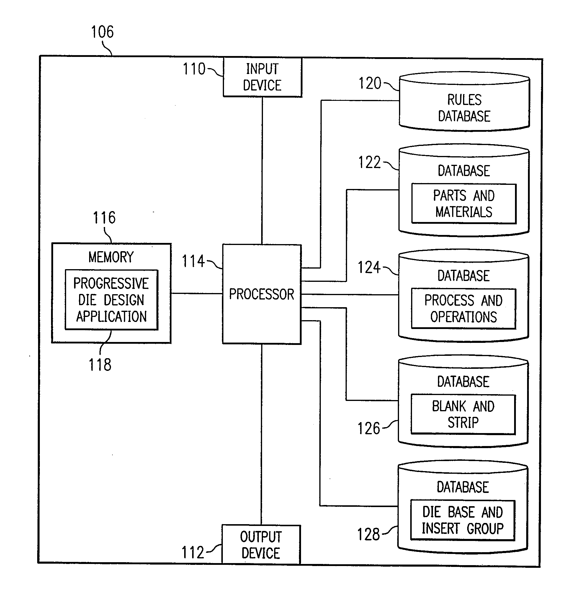
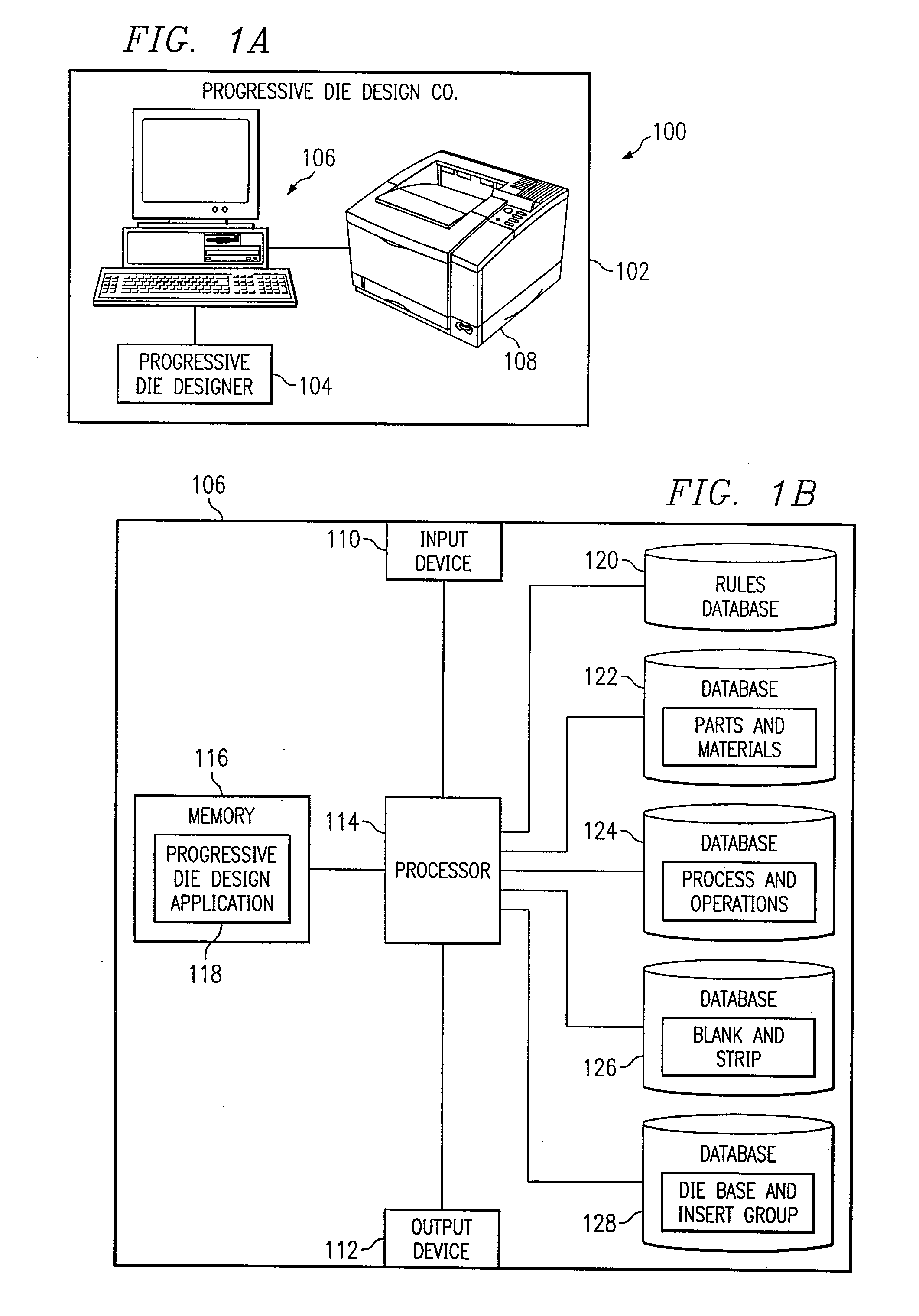
[0029]FIG. 1a is a block diagram illustrating a computer-aided progressive die design system 100 according to one embodiment of the present invention. System 100 includes a progressive die design company 102 employing a progressive die designer 104 having access to a computer 200 and a printer 108. Progressive die design company 102 may be any company or other suitable entity that designs progressive dies. Progressive die design company 102 often has a goal of producing high-quality progressive dies within short lead-times. Because progressive die design is a relatively complex and highly iterative process, the present invention provides a computerized method and system for designing progressive dies used in manufacturing parts formed from sheet metal. Some embodiments of the present invention ...


PUM

PropertyMeasurementUnit
widthaaaaaaaaaa
lengthaaaaaaaaaa
press forceaaaaaaaaaa

Abstract

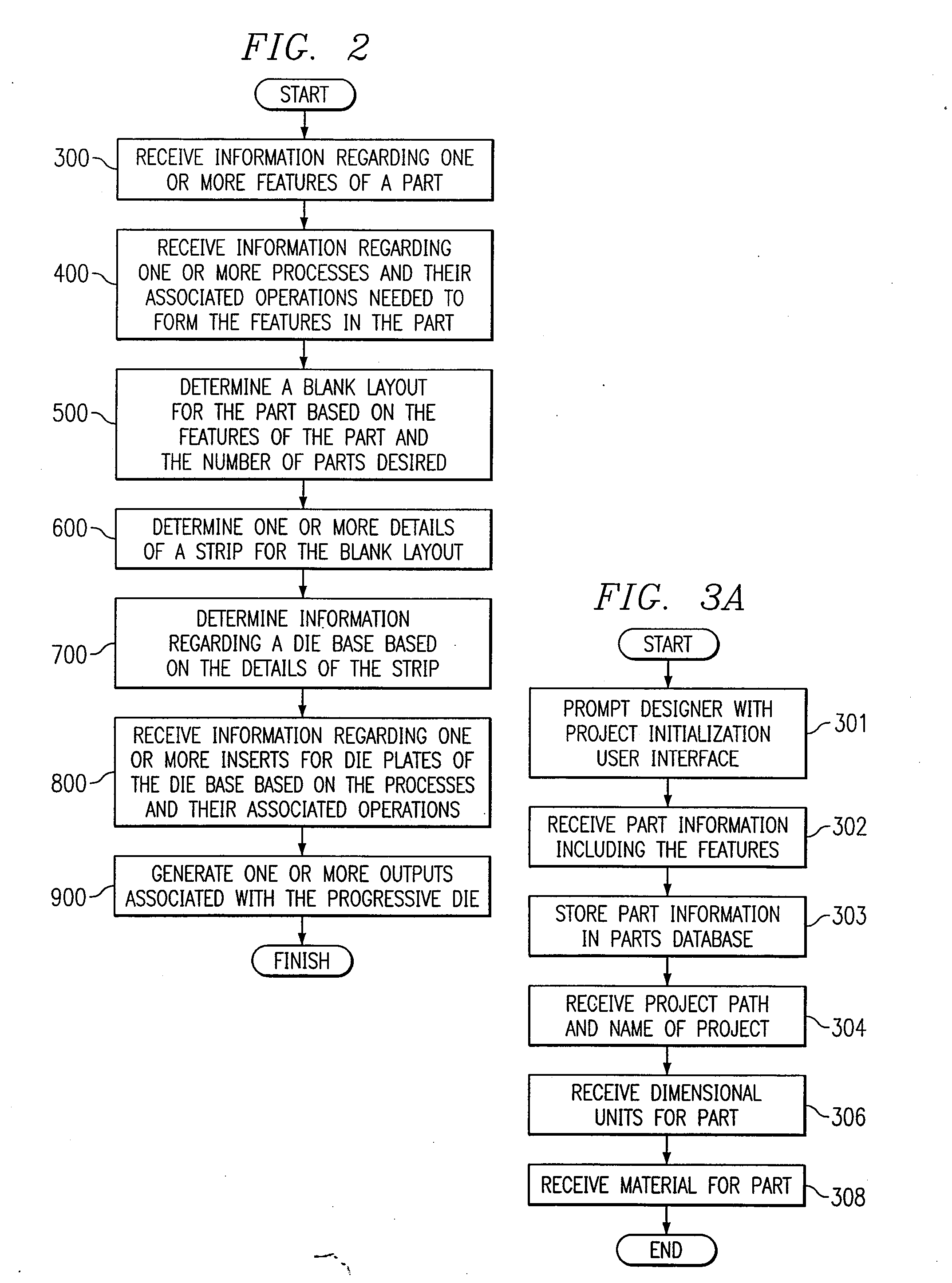
According to one embodiment of the invention, a computerized method for designing a progressive die used in the manufacturing of a part formed from sheet metal includes receiving, at a computer, information regarding one or more features of the part, and determining, by the computer, a blank layout for the part based on the features of the part and the number of parts desired. The computer further determines one or more details of a strip for the blank layout, information regarding a die base based on the details of the strip, and information regarding one or more inserts for die plates of the die base based on operations of the processes needed to form the features in the part. The computerized method further includes generating, by the computer, one or more outputs associated with the progressive die.

Description

RELATED APPLICATIONS [0001] This application is a continuation application of U.S. application Ser. No. 10 / 039,188 filed Dec. 31, 2001.TECHNICAL FIELD OF THE INVENTION [0002] The present invention relates generally to the computer-aided design (“CAD”) industry and, more particularly, to a computer-aided progressive die design system and method. BACKGROUND OF THE INVENTION [0003] Progressive dies are used to transform flat strips of sheet metal into a formed part. This transformation is performed progressively by a series of stations that cut, punch, form, and bend the material into a desired shape. A progressive die that performs the various forming operations on the material is unique for every part. The various components that make up the die are located in guided and precision cut openings in plates, which are in turn located and guided by pins. The entire die is actuated by a mechanical press that moves the die up and down, and the sheet metal is fed through the die progressing ...

Claims


Application Information

Patent Timeline
Patent Type & Authority Applications(United States)
IPC IPC(8): H01R13/73G05B19/4097G06F19/00
CPCG05B19/4097G05B2219/35044G05B2219/35156Y10T29/49279Y10T29/49291Y10T29/49798G05B2219/45204G06F30/17G06F2113/24Y02P80/40Y02P90/02
Inventor LIU, SHENGMING
Owner SIEMENS PROD LIFECYCLE MANAGEMENT SOFTWARE INC
Learn More