Antenna device

a technology of antenna and resonant element, which is applied in the direction of resonant antenna, resonant antenna, loop antenna with ferromagnetic core, etc., can solve the problems of difficult to dispose of antenna, difficult to achieve efficient layout, and difficult to dispose antenna, so as to reduce the influence of planar conductor, improve the durability and designability of mobile wireless devices, and achieve efficient layout

Inactive Publication Date: 2017-01-05
TDK CORPARATION
View PDF28 Cites 7 Cited by
  • Summary
  • Abstract
  • Description
  • Claims
  • Application Information

AI Technical Summary

Benefits of technology

[0022]In the above invention, it is preferable that the planar coil antenna is housed inside a housing of a mobile wireless device, and that the planar conductor constitutes a part of the housing. When the housing of the mobile wireless device is constituted of the planar conductor, durability and designability of the mobile wireless device can be improved; however, a shielding effect of the planar conductor may disable the communication function of the antenna device. According to the present invention, such a problem can be solved, and it is possible to realize wireless communication using the planar coil antenna by suppressing influence of the planar conductor.
[0023]In the above invention, the planar conductor is preferably a high-frequency antenna. When both the planar coil antenna and high-frequency antenna are mounted in the housing of the mobile wireless device, layout thereof becomes a problem. However, according to the present invention, it is possible to efficiently lay out both the planar coil antenna and high-frequency antenna within a limited space inside the housing of the mobile wireless device while ensuring satisfactory antenna characteristics of the planar coil antenna and high-frequency antenna.
[0024]According to the present invention, there can be provided an antenna device allowing the planar coil antenna and high-frequency antenna to be efficiently laid out in a limited space inside the housing of the mobile wireless device while ensuring satisfactory antenna characteristics of the planar coil antenna and high-frequency antenna.

Problems solved by technology

However, the metal shield blocks radio waves in general, so that when an antenna needs to be provided, it needs to be disposed at a position not covered with the metal shield.
Thus, when the metal shield covers a wide area, it is difficult to dispose the antenna.
In a case where the housing itself of the mobile wireless device serves also as the metal shield as described above, it is necessary to dispose an antenna at a position not covered with the metal shield, and when the metal shield covers a wide area, it is difficult to dispose the antenna.
In particular, when both a planar coil antenna for NFC and a high-frequency antenna used for UHF band wireless communication are mounted, it is very difficult to achieve efficient layout while ensuring desired antenna characteristics.
When both the planar coil antenna and high-frequency antenna are mounted in the housing of the mobile wireless device, layout thereof becomes a problem.

Method used


Image

  • Antenna device
  • Antenna device
  • Antenna device

Examples


first embodiment

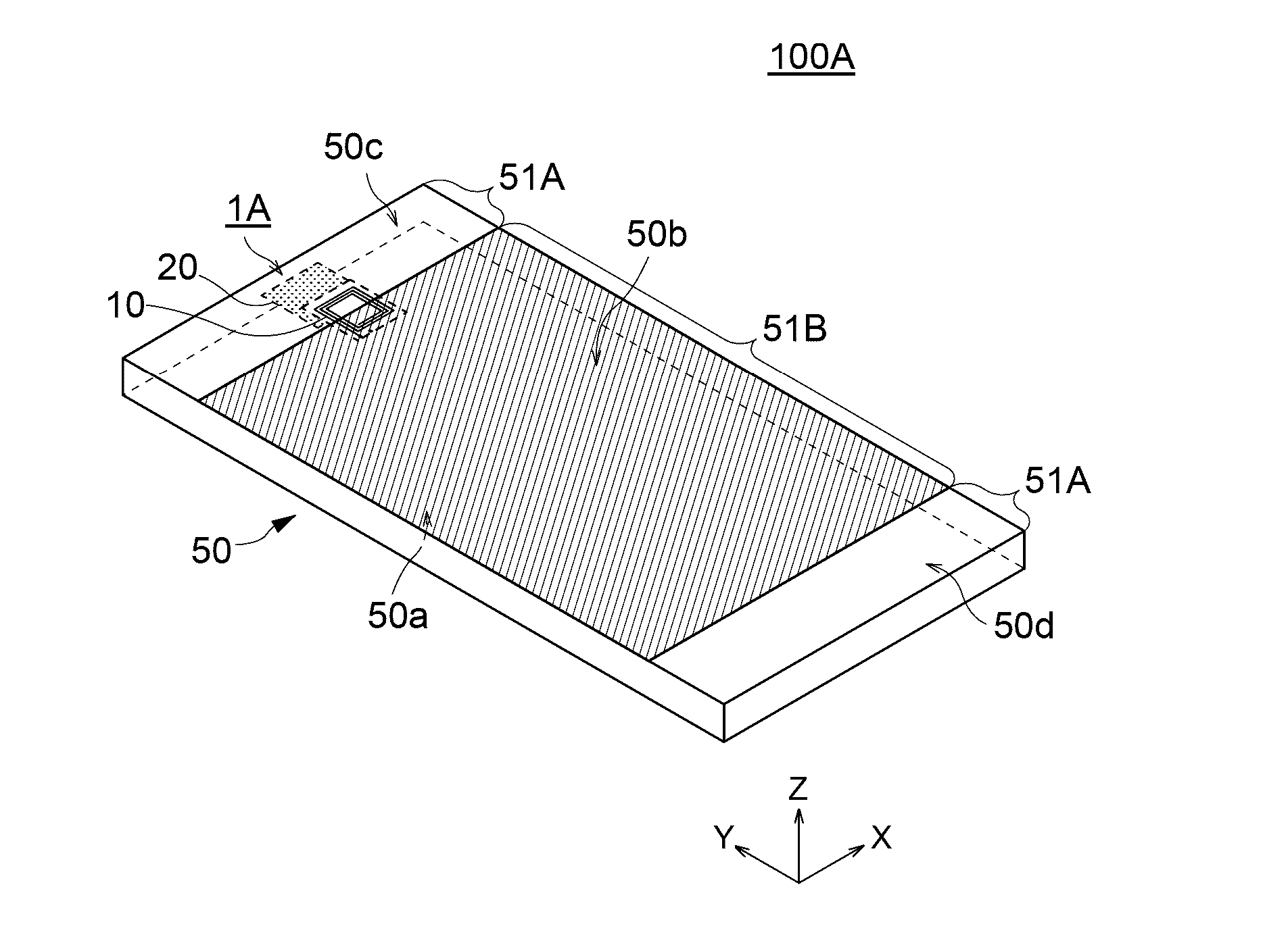
[0046]FIG. 1 is a schematic perspective view illustrating a configuration of a mobile wireless device 100A including an antenna device according to the present invention.

[0047]As illustrated in FIG. 1, a mobile wireless device 100A according to the present embodiment is, e.g., a smartphone and has a very thin housing 50. In FIG. 1, a back surface 50b of the housing 50 faces upward, and a front surface 50a of the housing 50 on which a display is mainly disposed faces downward. The housing 50 is made of a combination of a resin and a metal, and a metal cover layer 51B is formed in a wide area thereof including a center portion of the back surface 50b. Further, a resin cover layer 51A is formed on one end portion (upper end portion 50c) and the other end portion (lower end portion 50d) of the back surface 50b of the housing 50 in a longitudinal direction (Y-direction). The resin cover layer 51A is a non-shielded region where the metal cover layer 51B is not formed. The metal cover laye...

second embodiment

[0074]FIGS. 5A and 5B are plan views each transparently illustrating a configuration of an antenna device 2A according to the present invention. FIG. 5A illustrates a state where the housing 50 (especially, metal cover layer 51B) is present, and FIG. 5B illustrates a state where the housing 50 is omitted. FIG. 6 is a cross-sectional view of the antenna device 2A taken along a line A-A of FIGS. 5A and 5B.

[0075]As illustrated in FIGS. 5A and 5B and FIG. 6, the antenna device 2A has a feature in that the high-frequency antenna 20 is disposed on the one main surface 10a side of the planar coil antenna 10. Other configurations are the same as those of the first embodiment.

[0076]When the high-frequency antenna 20 is disposed on the one main surface 10a side of the planar coil antenna 10, a part of the planar coil antenna 10 is covered with the high-frequency antenna 20 in a plan view, a shielding effect by the high-frequency antenna 20 poses a problem. That is, a planar conductor constitu...

third embodiment

[0081]FIG. 7 is a schematic cross-sectional view of an antenna device 3A according to the present invention.

[0082]As illustrated in FIG. 7, the antenna device 3A has a feature in that the high-frequency antenna 20 constitutes a part of the housing 50 of the mobile wireless device. That is, in the present embodiment, apart of the metal cover layer 51B constituting the housing 50 is used as the high-frequency antenna 20. Other configurations are the same as those of the second embodiment. According to the present embodiment, in addition to the effects obtained by the second embodiment, it is possible to eliminate the need to ensure amounting space of the high-frequency antenna 20 inside the housing 50, thereby enhancing a degree of freedom of layout of the planar coil antenna 10. Further, there is no member that influences electromagnetic waves to be radiated from the high-frequency antenna 20 outside the high-frequency antenna 20, so that radiation characteristics of the high-frequen...


PUM


Abstract

Disclosed herein is an antenna device that includes a planar coil antenna, a high-frequency antenna that overlaps a part of the planar coil antenna in a plan view, and a magnetic sheet that overlaps another part of the planar coil antenna without overlapping the high-frequency antenna in a plan view.

Description

BACKGROUND OF THE INVENTION[0001]Field of the Invention[0002]The present invention relates to an antenna device and, more particularly, to an antenna device suitable for NFC (Near Field Communication).[0003]Description of Related Art[0004]In recent years, mobile wireless devices typified by smartphones have various communication functions such as wireless LAN, Bluetooth, GPS, and NFC, as well as a telephone and data communication functions.[0005]Such a mobile wireless device is provided with a metal shield in order to protect a built-in circuit from external noise and prevent unnecessary radiation of noise generated inside the device. In particular, recently, in view of thinning, light-weighting, durability against impact at the time of falling, and designability, a housing itself of the mobile wireless device is often made of a metal instead of a resin and serves also as the metal shield. However, the metal shield blocks radio waves in general, so that when an antenna needs to be p...

Claims


Application Information

Patent Timeline
Patent Type & Authority Applications(United States)
IPC IPC(8): H01Q1/24H01Q1/50H01Q1/22H04B5/00H01Q1/38H01Q9/28
CPCH01Q1/243H01Q7/06H01Q9/0407H04B5/0031H04B5/0081H04B5/00
Inventor KOMACHI, TOSHIFUMIASOU, HIROHUMITOMONARI, TOSHIO
Owner TDK CORPARATION
Why Eureka
Try Eureka