
System and method for generating test cases

a test case and test system technology, applied in the field of software design and development system for software testing, can solve problems such as combinatorial explosion, complex problem of developing an effective and efficient set of test cases, and combinatorial explosion

Inactive Publication Date: 2006-11-23
IBM CORP
View PDF3 Cites 80 Cited by
  • Summary
  • Abstract
  • Description
  • Claims
  • Application Information

AI Technical Summary

Benefits of technology

[0023] Another exemplary embodiment of the present invention uses a planning algorithm to create test cases that attempt to reach goal states. The use of a planning algorithm is advantageo...

Problems solved by technology

When testing software systems, developing an effective and efficient set of test cases is a complex problem.
So, there are at least two places where one runs into a large number of combinations, which leads to a combinatorial explosion problem.
These methods suffer from problems dealing with combinatorial explosion.
Also, these techniques are very hard to optimize from an internal state-based viewpoint.
An additional difficulty in finite-state based test generation is model representation.
Because the coverage focus of the test generation method is on a system state, models often require a very high degree of detail and can be difficult to construct.
These conventional techniques have at least two problems.
First, the representations that are conventionally used to capture the system in enough detail to be able to test it are typically arduous to capture and create.
This requires the user to supply unnecessary and complex information for managing the lifecycle of a particular entity such as its creation, deletion, and updates.
Also, the navigation through the arrays is done using low-level loop iterators, which adds to the complexity of the modeling effort.
This low level of construct also puts the onus of relationship management (such as creating and deleting a relationship between instances of two particular entities on the user, thus adding to the complexity of the model building task.
Second, these techniques almost universally suffer from state explosion problems.
Some techniques for avoiding finite-state space explosion exist however, these techniques require detailed knowledge and precise specification that is beyond the capability of the typical tester.
However, this requires additional knowledge about what interesting states and transitions are to be included and excluded, and creates another level of complexity for the user.
Another problem for conventional techniques is a lack of system state verification.
Each operation that updates the state of the system could do so in error.

Method used


Image

  • System and method for generating test cases
  • System and method for generating test cases
  • System and method for generating test cases

Examples


Embodiment Construction

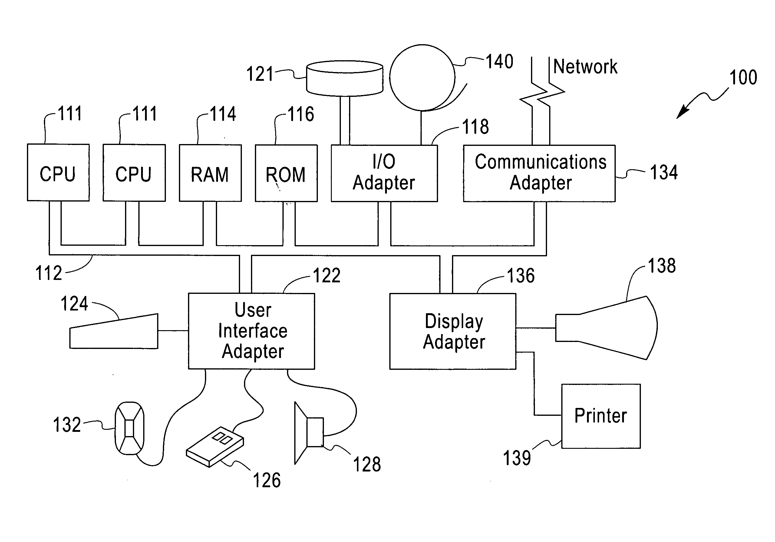
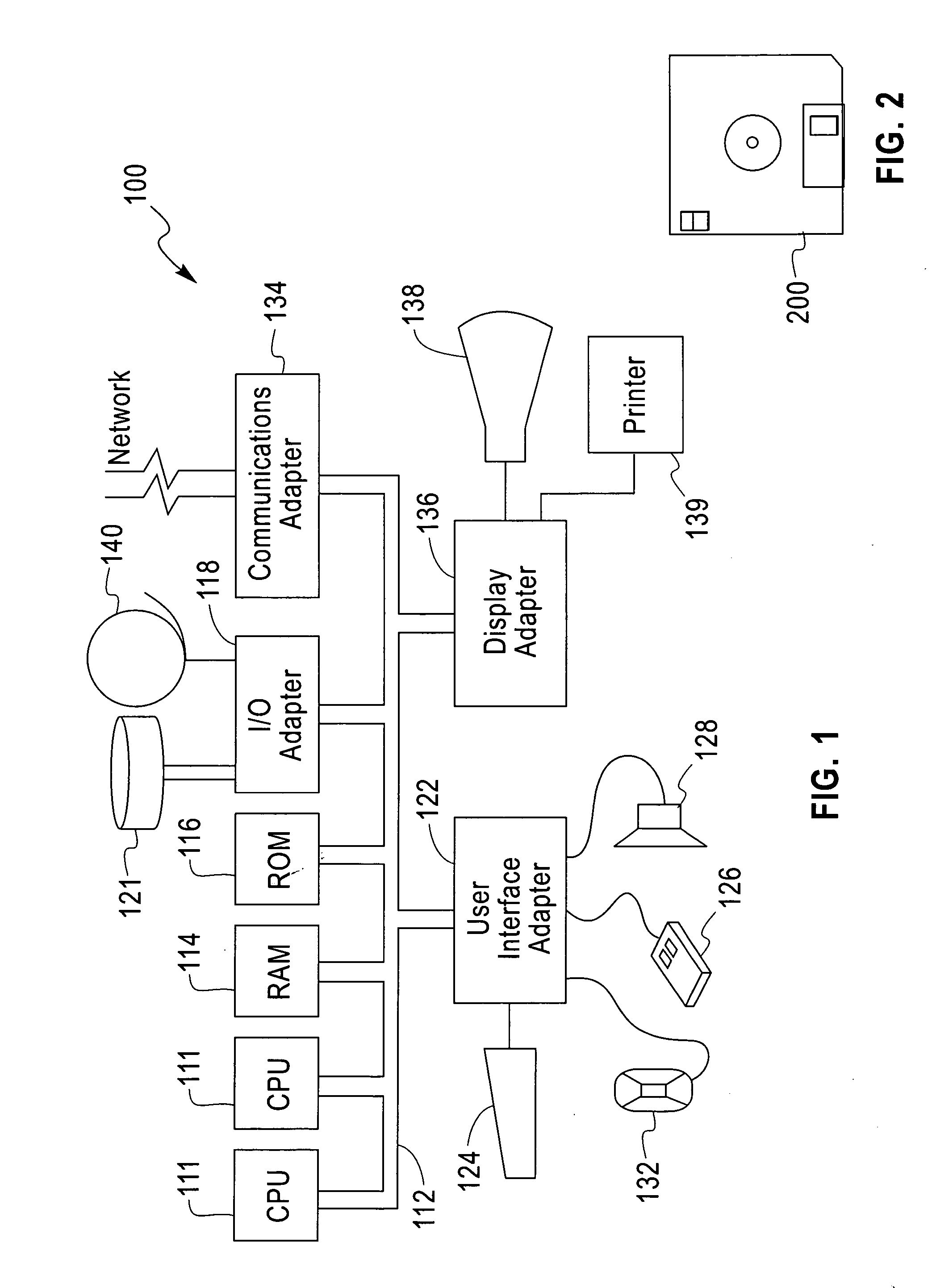
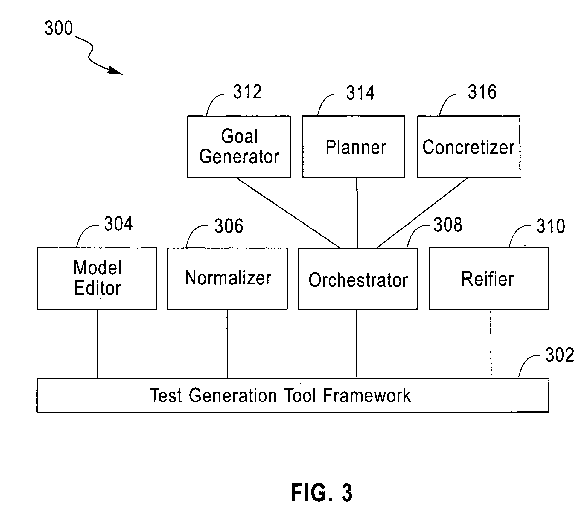
[0044] Referring now to the drawings, and more particularly to FIGS. 1-13, there are shown exemplary embodiments of methods and structures in accordance with the present invention.

[0045] An exemplary embodiment of the present invention uses the concept of a use case that defines a piece of functionality, which is of interest to a user. In other words, the use case presents the tested system in a manner that is similar to a user view of that system. For example, in a word processor a user might want to save a file. The user thinks, “I am going to save a file.” Thus, “save file” becomes a use case. A use case may include several steps. In this example, the user might click “save as”, type the filename and then click “OK.” The system might respond with “That file name already exists, do you want to overwrite it?” and the user responds “Yes.” Thus, there are many operations that might happen for a particular use case. Those steps are actions within the use case.

[0046] There is another...


PUM


Abstract

A method and system for automatically generating a test case for object-oriented software includes providing a model of the object-oriented software, determining a test state for the object-oriented software, and determining a sequence of test steps for the object-oriented software based upon the test state.

Description

BACKGROUND OF THE INVENTION [0001] 1. Field of the Invention [0002] The present invention generally relates to a software design and development system for software testing. In particular, the present invention relates to methods and systems for generating test cases. [0003] 2. Description of the Related Art [0004] When testing software systems, developing an effective and efficient set of test cases is a complex problem. A suite of test cases is effective if it thoroughly covers combinations of inputs, actions, and sequences of actions, enhancing the likeliness it will encounter defects in the software. A suite is efficient if it provides such coverage without unnecessary redundancy, which would unduly increase the testing effort. [0005] Typically, when a tester tests a software system, the tester or test program takes an action against the system being tested and receives a result or response back from the tested system. The received result is compared against an expected result t...

Claims


Application Information

Patent Timeline
IPC IPC(8): G06F9/44
CPCG06F11/3684
Inventor KLINGER, TAMIRPARADKAR, AMITKUMAR M.WILLIAMS, CLAY E.
Owner IBM CORP
Learn More