Sole structure for a shoe

Active Publication Date: 2006-11-30
MIZUNO CORPORATION
View PDF84 Cites 37 Cited by
  • Summary
  • Abstract
  • Description
  • Claims
  • Application Information

AI Technical Summary

Benefits of technology

[0037] In this case, the deformation of the convex portion of the lower plate on the lateral side of the heel region is more restricted than the deformation of the convex portion of the lower plate on the medial side. As a result, supination can be prevented at the time of sidestepping and the sole structure suitable for an indoor shoe such as a tennis shoe or basketball shoe can thus be achieved.
[0038] A longitudinally extending rib may be integrated with the upper pate or the lower plate. Since provision of a rib increases the bending rigidity of the upper or lower plate, deformation of the upper or lower plate is restrained, and the bending and cushioning properties can be adjusted.
[0039] The rib may be formed either on the medial side or the lateral side of the upper or lower midsole. In the case where the rib is provided on the medial side of the plate, pronation at the time of impacting the ground can be prevented and the sole structure suited for a running shoe can be proposed. In the case where the rib is provided on the lateral side of the plate, supination at the time of sidestepping can be prevented and the sole structure suited for an indoor shoe such as a tennis shoe or a basketball shoe can be proposed.
[0040] The number of ribs may be different between the medial side and the lateral side of the upper or lower plate. In this case, since the bending rigidity of the plate is made greater on the side with more ribs than the other side, by increasing the number of ribs on the medial side, a sole structure suitable for a running shoe can be attained. Alternatively, by increasing the number of ribs on

Problems solved by technology

However, in the prior art structure shown in JP publication No. 2003-339405, since the upper convex portions and the lower convex portions of the wavy plate are fixedly attached to the upper plate and the lower plate, respectively, a vertical deformation of the wavy plate has been restricted at the time of striking onto the ground.
Therefore, the prior art structure had the limitation on improvement in cushioning properties of t

Method used


Image

  • Sole structure for a shoe
  • Sole structure for a shoe
  • Sole structure for a shoe

Examples


first embodiment

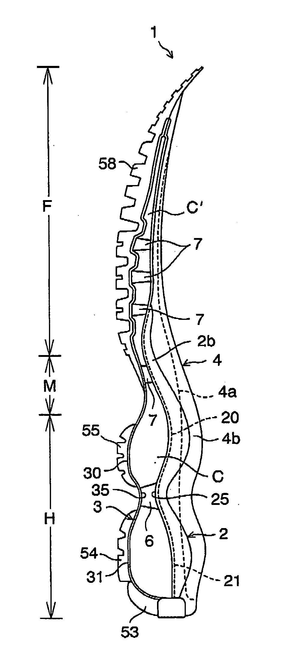
[0060] Referring now to the drawings. FIGS. 1A and 1B show a sole structure or a sole assembly according to the present invention. As shown in FIGS. 1A and 1B, a sole structure 1 includes an upper plate 2 extending from a heel portion H through a midfoot portion M to the forefoot portion F of the sole structure 1, and a lower plate 3 disposed below the upper plate 2 and extending from the heel portion H through the midfoot portion M to the forefoot portion F similar to the upper plate 2. Both of the upper plate 2 and the lower plate 3 extend in the shoe width direction, and the front end edges of the plates 2, 3 are coupled to each other and rear end edges of the plates 2, 3 are also coupled to each other.

[0061] The upper plate 2 has wavy configurations that progress longitudinally in the heel portion H and that have two convex portions 20, 21 each protruding upwardly. The lower plate 3 has wavy configurations that progress longitudinally in the heel portion H similar to the upper p...

second embodiment

[0076]FIG. 3 shows a sole structure according to the present invention. In FIG. 3, like reference numbers indicate identical or functionally similar elements.

[0077] In the above-mentioned first embodiment, the upwardly convex portion 35 between the adjacent downwardly convex portions 30, 31 of the lower plate 3 is positioned against the downwardly convex portion 25 between the adjacent upwardly convex portions 20, 21 of the upper plate 2, whereas in the second embodiment, these convex portions 25, 35 are disposed offset in the longitudinal direction. Preferably, as shown in FIG. 3, the downwardly convex portion 25 of the upper plate 2 is disposed in front of the upwardly convex portion 35 of the lower plate 3. An elastic block 6 connecting the downwardly convex portion 25 of the upper plate 2 with the upwardly convex portion 35 of the lower plate 3 extends obliquely upwardly from the lower plate 3 to the upper plate 2.

[0078] In this case, at the time of striking onto the ground, th...

third embodiment

[0080]FIG. 4 shows the present invention. In FIG. 4, like reference numbers indicate identical or functionally similar elements.

[0081] This third embodiment differs from the second embodiment in that the upper and lower plate 2, 3 has a third convex portion 22, 32, respectively. The convex portions 22, 32 protruding in the opposite directions are contraposed in the vertical direction, and a third void C is formed between the convex portions 22, 32. The upwardly convex portion between the adjacent downwardly convex portions 31, 32 of the lower plate 3 is disposed opposite the downwardly convex portion between the adjacent upwardly convex portions 21. 22 of the upper plate 2. These oppositely disposed portions are connected to each other through the elastic block 61.

[0082] In this case, by forming the void C at the heel rear end portion, when impacting the ground on the heel rear end portion, downward deformation of the upper plate 2 becomes much easier, thereby further improving the...


PUM


Abstract

A sole structure is provided that can improve cushioning and bending properties of the sole heel portion. The sole assembly 1 is formed of an upper plate 2 disposed on the upper side of the heel portion H, a wavy lower plate 3 provided below the upper plate 2 in the heel portion H and having at least two convex portions 30, 31 that protrude downwardly and that are adapted to form voids C relative to the upper plate 2, and a plurality of outsole portions 51-55 that are divided in the longitudinal direction and that are attached to the lower surfaces of the convex portions 30, 31 of the lower plate 3.

Description

BACKGROUND OF THE INVENTION [0001] The present invention relates generally to a sole structure for a shoe, and more particularly, to an improvement in the sole structure for enhancing cushioning and bending properties of the heel portion of the sole. [0002] Japanese patent application laying-open publication No. 2003-339405 shows a sole structure for a shoe to secure cushioning properties of the heel portion. In the sole structure, an upper plate and a lower plate are disposed on the upper side and the lower side, respectively, of a wavy plate that is disposed at the heel region. [0003] In this case, a plurality of voids formed between the wavy plate and the upper and lower plate function as cushion holes to secure cushioning properties of the heel portion. [0004] However, in the prior art structure shown in JP publication No. 2003-339405, since the upper convex portions and the lower convex portions of the wavy plate are fixedly attached to the upper plate and the lower plate, resp...

Claims


Application Information

Patent Timeline
IPC IPC(8): A43B13/28
CPCA43B13/10A43B13/12A43B13/183A43B13/145A43B13/146A43B13/141
Inventor KITA, KENJIROODA, TAKAOMIYAUCHI, AKIHIRO
Owner MIZUNO CORPORATION
Why Eureka
Try Eureka