Arrangement for precision balancing the rotor of a gas turbine engine

a technology of gas turbine engine and rotor, which is applied in the direction of measurement devices, structural/machine measurement, instruments, etc., can solve the problems of reducing affecting the efficiency of the engine, and affecting so as to achieve the effect of extending the service life of the engine, low cost and small weigh

Inactive Publication Date: 2006-11-30
ROLLS ROYCE DEUT LTD & CO KG
View PDF8 Cites 22 Cited by
  • Summary
  • Abstract
  • Description
  • Claims
  • Application Information

AI Technical Summary

Benefits of technology

[0009] Thus, with little effort, it is possible to remove any residual imbalances when the engine is assembled, e.g., after final assembly or repairs, and thus to extend a service life of the engine. In addition, the balancing is performed in an optimum range in terms of rotor dynamics which means that it can be effected with little additional weight far out at the rotor disks and in a medium portion of the rotor. Existing engines can easily be retrofitted with the balancing system as existing circumferential grooves are utilized. The system only requires low costs and small weights as compared to other balancing systems.

Problems solved by technology

Improperly balanced rotors can cause bending of the shaft which may result in gap bridging and contact of the rotor with static parts.
The running gaps thus developing result in efficiency loss.
In addition, undesirable vibrations occur that cause early bearing wear or acute bearing damage.
This can shorten the service life of the rotor components considerably.
After the engine has been fully assembled with its rotor being housed in inner and outer cases, only minor adjustments of the low-pressure shaft can be performed while precision balancing, i.e., removing residual imbalances of the high-pressure shaft that can only be accessed with difficulty when the gas turbine engine is assembled and the rotors are encompassed by the outer and inner cases, is virtually unfeasible or requires considerable effort.
A residual imbalance of the high-pressure shaft can result in considerable vibration and the resulting damages.
Such an arrangement has the disadvantage that the band has a relatively heavy weight and accessibility via the gas path is only provided to the first rotor stage on the compressor.
This does not allow for efficient rotor dynamics and requires accordingly great weights.

Method used


Image

  • Arrangement for precision balancing the rotor of a gas turbine engine
  • Arrangement for precision balancing the rotor of a gas turbine engine
  • Arrangement for precision balancing the rotor of a gas turbine engine

Examples


Embodiment Construction

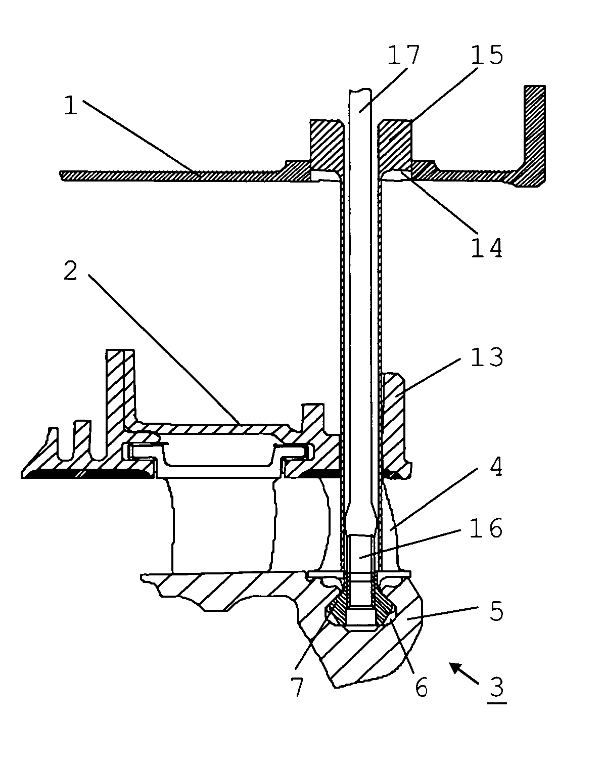
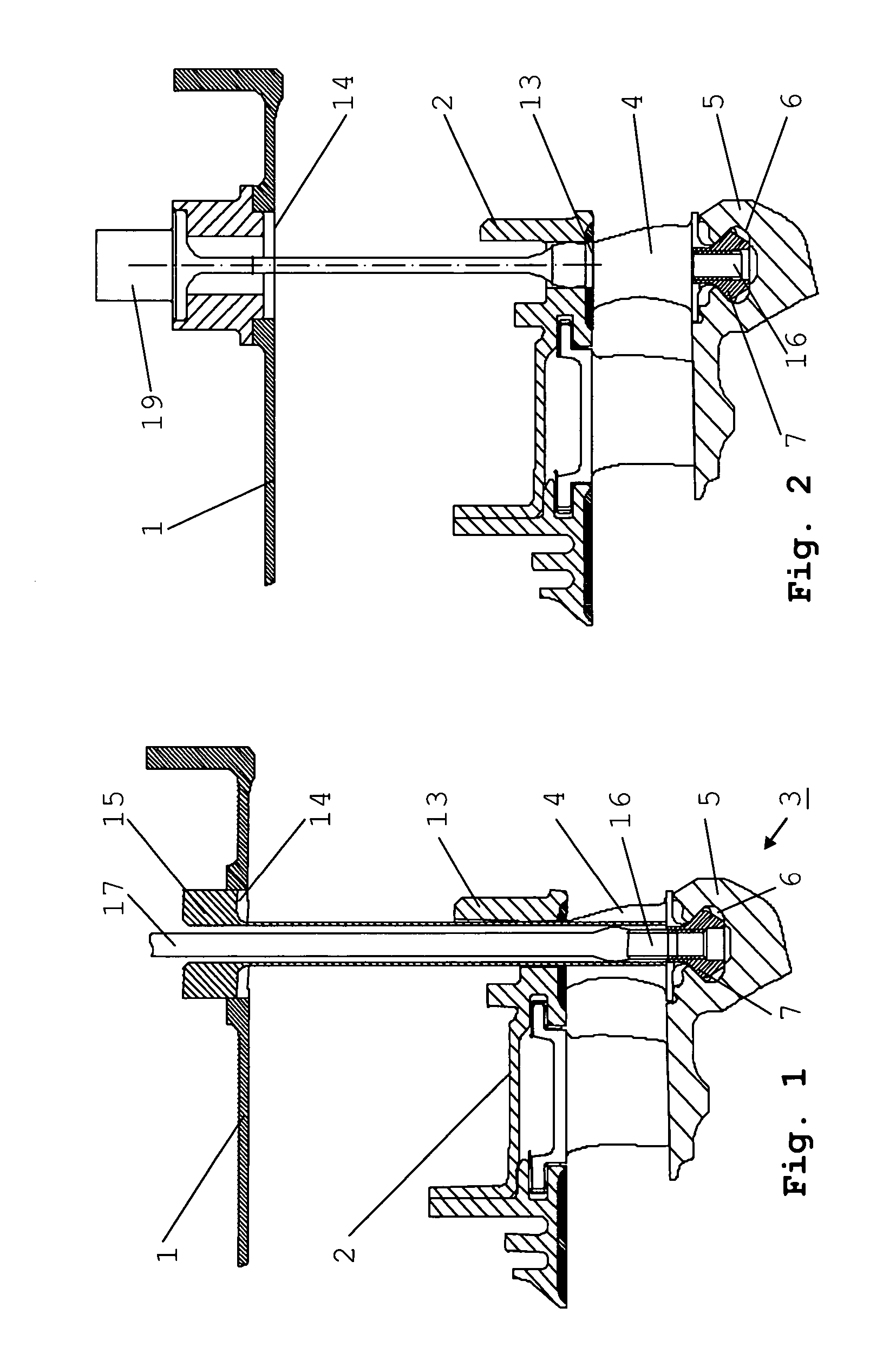
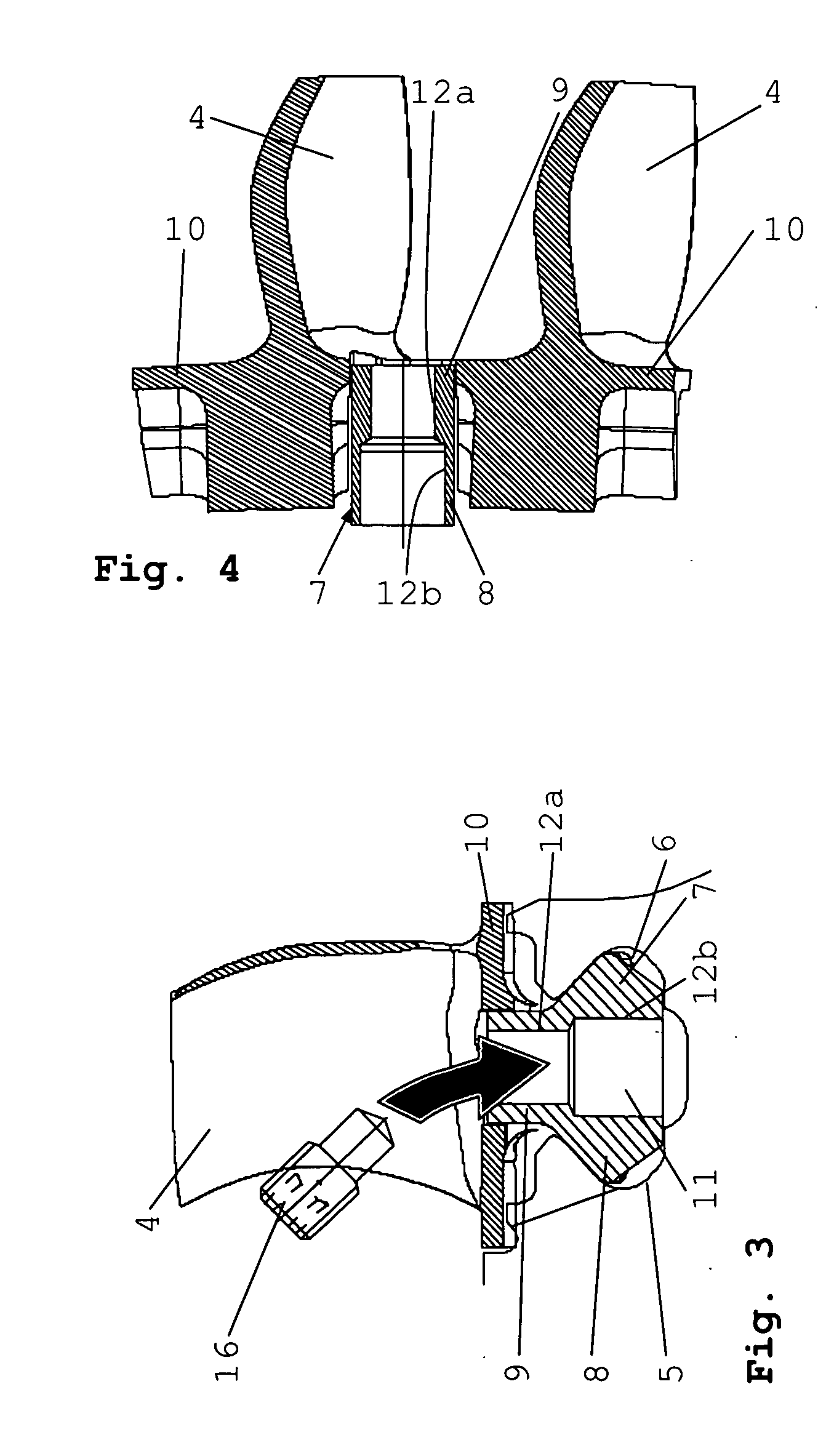
[0019] In the engine shown in the figures, reference symbol 1 denotes the outer case, 2 the inner case and 3 the rotor, or more precisely, a rear rotor stage of the compressor. Rotor blades 4 are inserted into a circumferential groove 6 provided on the outer surface of a rotor disk 5 of this rear rotor stage. The circumferential groove 6 houses multiple inserts 7 placed at an even spacing around its perimeter. The insert 7 includes a base part 8 that matches the cross-sectional shape of the circumferential groove 6, a threaded part 9 encompassed by opposite recesses of two adjacent platforms 10 of adjacent rotor blades 4, and a hole 11 with a female threaded section 12a. Other components of the precision-balancing arrangement are a first opening 13 in the inner case 2 and a second opening 14 in the outer case 1 that is vertically aligned with the first opening 13. In a certain rotational position of the rotor 3, the holes 11 are in line with the first and second openings 13, 14 so t...


PUM


Abstract

For precision balancing of the rotor (3) that, in fully assembled condition of a gas turbine engine, is encompassed by an inner and an outer case, inserts (7) with a through hole (11) and a female threaded section are positioned at an even spacing in at least one circumferential groove (6) of the rotor disks (5) that receives the roots of the rotor blades (4). A temporarily installed guide tube (15) that runs through the openings (13, 14) connects to the through hole that in a certain rotor position is in line with the openings (13, 14) in the inner and outer cases (1, 2) for inserting and screwing in a balancing screw (16).

Description

[0001] This application claims priority to German Patent Application DE 10 2005 025 086.6 filed May 26, 2005, the entirety of which is incorporated by reference herein. BACKGROUND OF THE INVENTION [0002] This invention relates to an arrangement for precision balancing a rotor of a gas turbine engine while in its fully assembled state and encompassed by outer and inner cases. [0003] The rotors of compressors and turbines of a gas turbine engine rotate at a very high speed. Improperly balanced rotors can cause bending of the shaft which may result in gap bridging and contact of the rotor with static parts. The running gaps thus developing result in efficiency loss. In addition, undesirable vibrations occur that cause early bearing wear or acute bearing damage. This can shorten the service life of the rotor components considerably. It is known that rotors are balanced by adding weights to, or removing material from, the rotating components. [0004] The rotors of a gas turbine engine tha...

Claims


Application Information

Patent Timeline
Patent Type & Authority Applications(United States)
IPC IPC(8): G01M1/16
CPCF01D25/285F01D5/027
Inventor PICHEL, SACHAJAHNS, INGOWIRTH, MORITZ
Owner ROLLS ROYCE DEUT LTD & CO KG
Why Eureka
Try Eureka