Tool with protective sheath

a protective sheath and tool technology, applied in the field of tools having a protective sheath or cover, can solve the problems of affecting the appearance of finished surfaces, so as to prevent the marring of finished surfaces

Inactive Publication Date: 2006-11-30
INT PAPER CO
View PDF34 Cites 19 Cited by
  • Summary
  • Abstract
  • Description
  • Claims
  • Application Information

AI Technical Summary

Benefits of technology

[0014] The invention comprises a protective sheath for tools, wherein the sheath is effective to prevent marring of finished surfaces and also provides a non-rotating surface that can be grasped by a worker to support and guide the tool without affecting the torque output of the tool, that covers connections or joints between connected parts of the tool, and that covers flexible portions of the tool, such as flex shafts, swivel connectors and adapters, and the like.
[0016] In a preferred embodiment, the sheath extends throughout the length of the tool and projects slightly beyond both ends of the tool. However, the sheath can have a length such that it does not project beyond the ends of the tool, or it can project beyond one or both ends up to a distance that does not interfere with use of the tool. In those embodiments where an end of the sheath projects beyond that end of the tool that engages the fastener, the projecting end will contact a finished surface and prevent contact between the tool and the surface, thereby preventing marring of the surface. The end of the sheath projecting beyond the opposite end of the tool will cover the connection or joint between the tool and another tool part, such as an extension, and minimize or prevent the risk of hair, clothing, jewelry, and the like, becoming entangled in the connection as the tool rotates.
[0018] The sheath of the invention, whether applied to a socket or an extension or other tool part, is freely rotatable on the tool and is constructed so that it can be grasped to provide a safe and comfortable means of holding and guiding the tool, and not affect the torque applied to a fastener with the tool, regardless of how tight the sheath is gripped. This is accomplished, at least in part, by making the sheath of a material having a low coefficient of friction. For instance, the effect on fastener torque when using the sheath of the invention is negligible in comparison with the effect of a gloved hand, i.e., the work required to overcome the friction of the sheath is only from about 0.1 Newton meter (Nm) to about 0.2 Nm, compared to about 0.3 to 0.6 Nm with a gloved hand. Further, the torque impact of the sheath on the tool part is substantially less than the impact of a gloved hand, i.e., 0.138 Nm versus 0.589 Nm when used on an extension, and 0.138 Nm versus 0.351 when used on a socket. The friction of the sheath on the tool part also is very consistent. No silicone is used in the manufacture of the sheath since this material can have a deleterious effect on the finished surface, for example.
[0019] In a preferred embodiment, the material comprises a composition of from about 60% to about 80% thermoplastic polyurethane, from about 1% to about 5% lubricant, from about 1% to about 4% epoxy additive, and from about 5% to about 20% thermoplastic polyester resin, with a hardness or durometer preferably in the range of from about 10 to about 90 on the d Shore scale. This formulation provides a sheath that is tough and stable, and that will allow the tool to rotate freely in the sheath under a variety of conditions.
[0023] In one embodiment of the invention, the sheath is adapted for use with tools that are designed to countersink fasteners, and has a wall section that deforms when the distal or forward end of the sheath engages a surface as the fastener is driven into the surface, thereby effectively retracting the forward end of the sheath so that the fastener can be countersunk with the tool without interference from the sheath.
[0024] In another embodiment, the sheath has a swivel or universal connection, enabling it to be used with universal joints or other swivel adapters and connections.

Problems solved by technology

These tools have hard metal surfaces, and in the case of screwdrivers or bits driven by power tools, for example, have relatively sharp or pointed edges that can easily mar the finished surface if they should slip off the fastener while it is being driven into place.
Sockets, nut drivers and the like can also mar the surface if they contact it, especially while they are rotating during the installation or removal of a fastener.
The level of care required to avoid contact between the tool and finished surface can impair productivity, or inevitably lead to damage, especially in an industrial environment where a large number of fasteners may need to be installed in a relatively short period of time.
Moreover, workers using power fastener tools typically hold or loosely grip the rotating portion of the tool to support and guide it while they are installing or removing a fastener.
In torque sensitive applications, gripping of the rotating portion of the tool by the worker can result in incorrect torque application to the fastener.
Further, because of this contact between the worker and the rotating portion of the tool, and the potential risk of the worker's hair becoming caught in the joint between attached components of the tool, such as, for example, between an extension and a socket, or between other joined together parts of the tool, injuries are not uncommon.
Conventional tools generally do not have any means to prevent contact between the hard metal surface of the tool and the finished surface, or between the worker and the rotating portions of the tool, although some efforts have been made in the prior art to solve the problem of marring finished surfaces.
Similarly, and although the coating applied to the Apex® tool is shown as applied to both the fastener-engaging portion of the tool, i.e., the socket or bit, and also to an extension, the coating is fixed relative to the tool and thus does not provide a non-rotating surface that can be grasped by the user to support and guide the tool without having to contact a rotating surface.
Neither is there any suggestion of providing means to enable the sleeve to be gripped without affecting the torque of the tool, that is, absorbing some of the energy output of the tool and potentially resulting in inadequate torque being applied to the fastener.
Further, none of the protective coverings known to applicant extend over flexible portions of the tool, such as over swivel connections or adapters, or over flex shafts and the like.

Method used


Image

  • Tool with protective sheath
  • Tool with protective sheath
  • Tool with protective sheath

Examples


Embodiment Construction

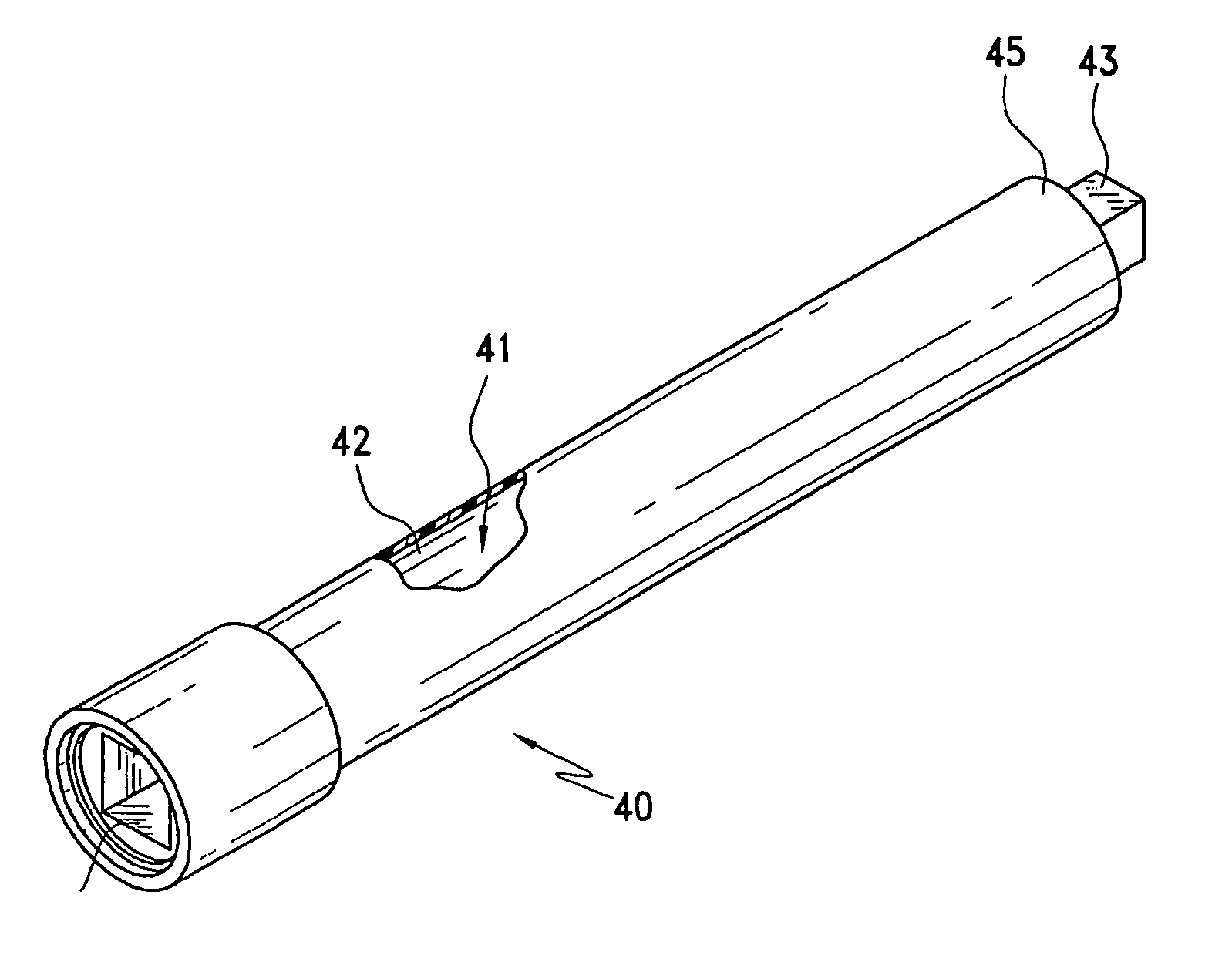
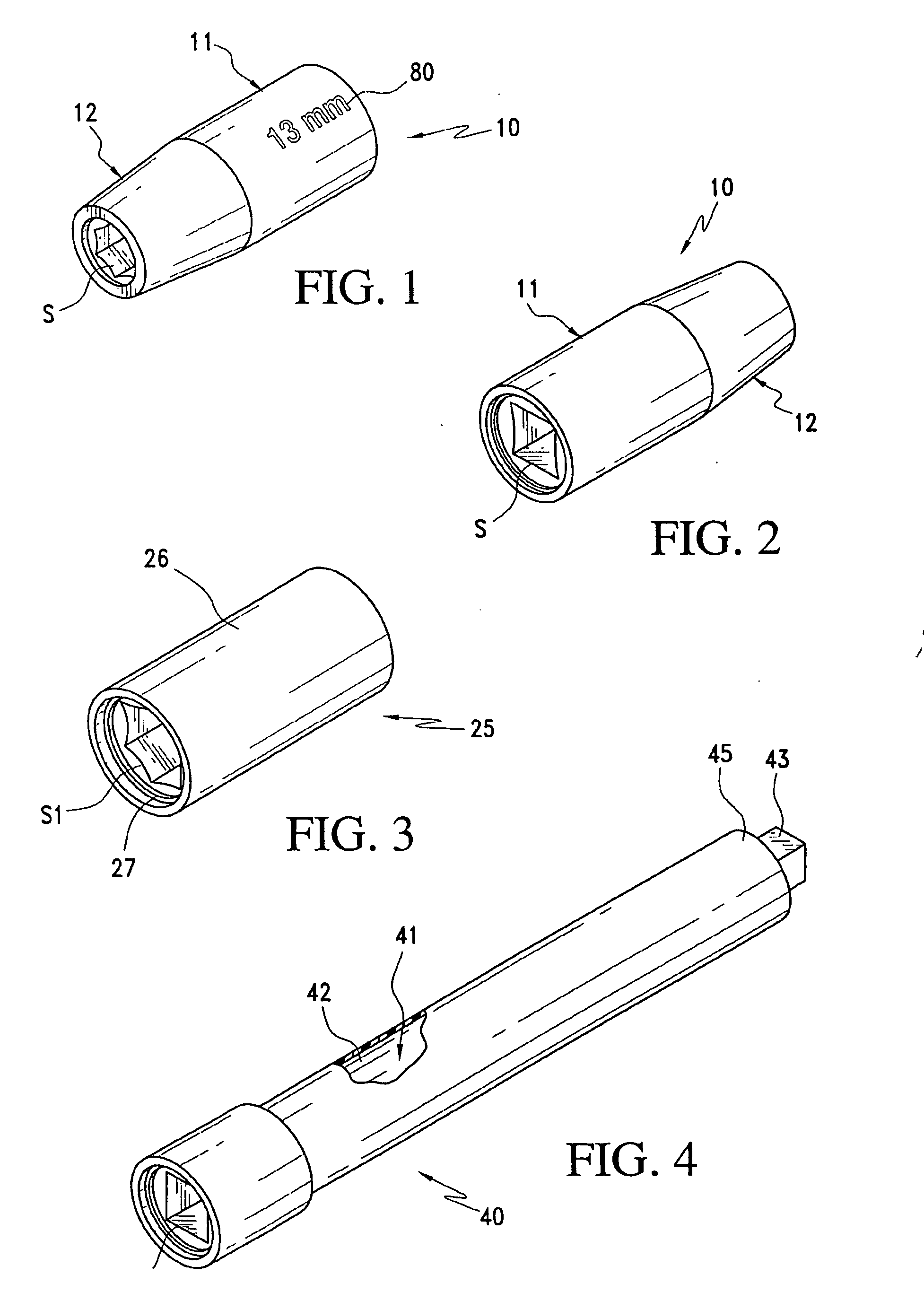
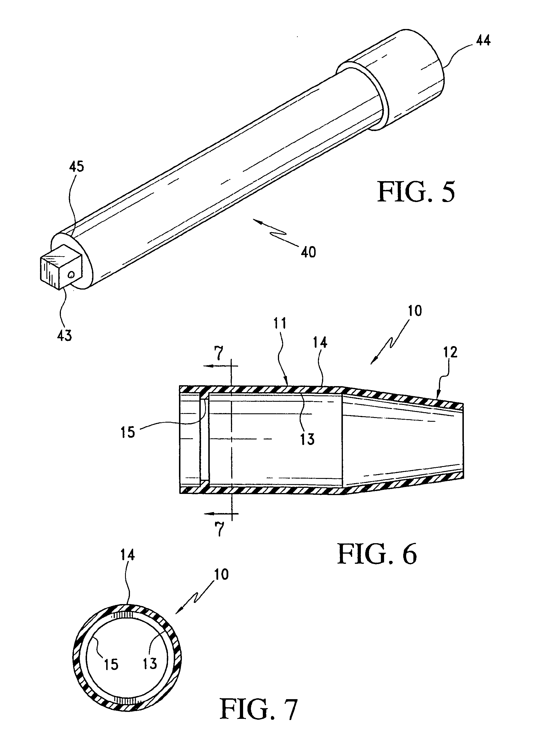
[0042] A first form of protective sheath according to the invention is indicated generally at 10 in FIGS. 1, 2, 6, 7 and 8, and as shown in these figures is applied to a socket S of the type sold by Cooper Tools under the name Apex®. In this embodiment, the socket has a cylindrical rearward or proximal end 11 and a slightly inwardly tapered forward or distal end 12, and the sheath 10 closely conforms to this shape. The wall of the sheath has a suitable thickness, e.g., about 5.334 mm throughout the length of the cylindrical section 11, and tapering from that thickness at the juncture of the cylindrical section 11 and tapered section 12 to about 3.33 mm at the distal or terminal end of the tapered section. The sheath has smooth inner and outer surfaces 13 and 14, respectively, and in the embodiment shown in these figures an inwardly projecting annular rib 15 is formed on its inner surface in position to extend into an annular channel or groove 16 formed in the outer surface of the so...


PUM


Abstract

A protective sheath for tools to prevent marring of finished surfaces when the tool is being used. The sheath is integrally formed as a one-piece elastomeric body that is applied to the exterior surface of the tool, with at least one end of the sheath projecting slightly beyond an end of the tool. In one embodiment the sheath projects at both ends beyond the ends of the tool. One of the projecting ends functions to contact the finished surface and prevent contact between the tool and finished surface, and the other projecting end functions to span the coupling between the tool and another tool. The elastomeric body is freely rotatable relative to the tool and fixed axially relative thereto, and provides a non-rotating surface that may be grasped by a user to support and guide the tool. Annular ribs on the inner surface of the sheath and / or a lubricant incorporated in the material of the sheath provide a reduction in friction, enabling the sheath to rotate freely on the tool even when it is grasped tightly by a person to support and guide the tool.

Description

CROSS-REFERENCE TO RELATED APPLICATIONS [0001] This application is a divisional of prior application Ser. No. 11 / 111,425, filed 21 Apr. 2005, now pending, and claims priority thereto under 35 USC 120. The written description of said '425 patent application is hereby incorporated hereinto by reference.BACKGROUND OF THE INVENTION [0002] This invention relates to tools having a protective sheath or cover to prevent damage to finished surfaces and minimize the risk of injury to workers. [0003] During the final assembly stages of many consumer products, including but not limited to appliances, automobiles, and the like, trim or finish pieces are commonly applied to the finished surfaces by inserting threaded fasteners through the trim or finish piece and into the finished surface. A worker typically applies these fasteners using various tools including screwdrivers, nut drivers, socket wrenches, and the like, or pneumatic or electric powered tools that drive various bits and / or sockets. ...

Claims


Application Information

Patent Timeline
Patent Type & Authority Applications(United States)
IPC IPC(8): B25B13/06
CPCB25B13/06B25B23/0021B25B23/0014B25B13/56
Inventor WEBER, JOSEPH C.
Owner INT PAPER CO
Why Eureka
Try Eureka