Endless conveyor belt and splicing member for forming same

a technology of conveyor belt and splicing member, which is applied in the direction of conveyors, transportation and packaging, etc., can solve the problems of increasing the likelihood of injury when the conveyor belt is assembled or operated, affecting the safety of workers, so as to reduce the likelihood of injury and/or snagging

Active Publication Date: 2006-11-30
LUMSDEN FLEXX FLOW
View PDF8 Cites 2 Cited by
  • Summary
  • Abstract
  • Description
  • Claims
  • Application Information

AI Technical Summary

Benefits of technology

[0007] A further object of a preferred embodiment of the present invention is to provide an endless conveyor belt that can be readily formed in the field.
[0009] Still a further object of a preferred embodiment of the present invention is to provide an endless conveyor belt that can be used for prolonged periods of time without the structural integrity of the conveyor becoming compromised.
[0011] Another object of a preferred embodiment of the present invention is to provide a conveyor belt that reduces the likelihood of snagging and / or injury.

Problems solved by technology

Snagging is undesirable as it can result in damage to the conveyor belt or other articles.
Further, snagging can cause unnecessary delay in assembling the belt.
Further, these spaces or gaps readily expose any burrs or jagged edges on the ends of the wire segments thereby increasing the likelihood of injury when the belt is assembled or operated.
These conveyor belts have significant disadvantages.
These designs lead to unnecessary delays in assembling the conveyor belt.
Further, the conveyor belt can become damaged or weakened during this process.

Method used


Image

  • Endless conveyor belt and splicing member for forming same
  • Endless conveyor belt and splicing member for forming same
  • Endless conveyor belt and splicing member for forming same

Examples


Embodiment Construction

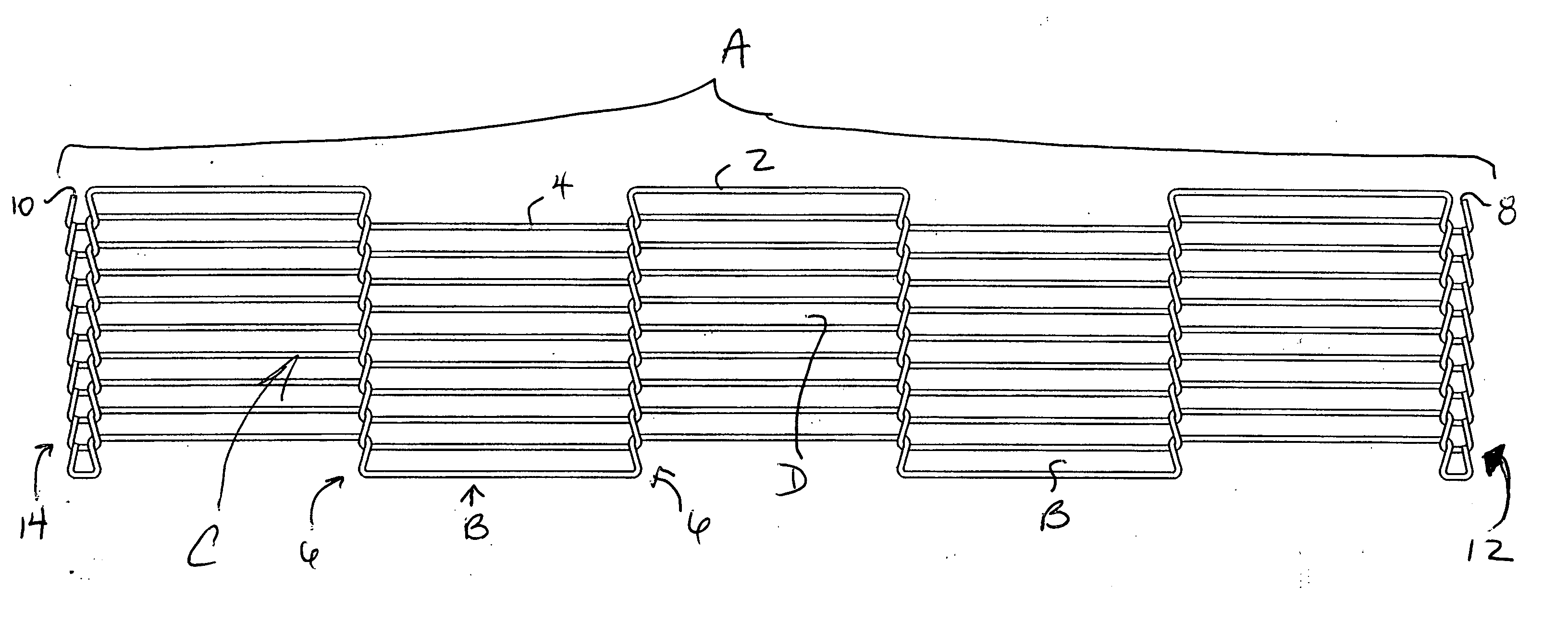
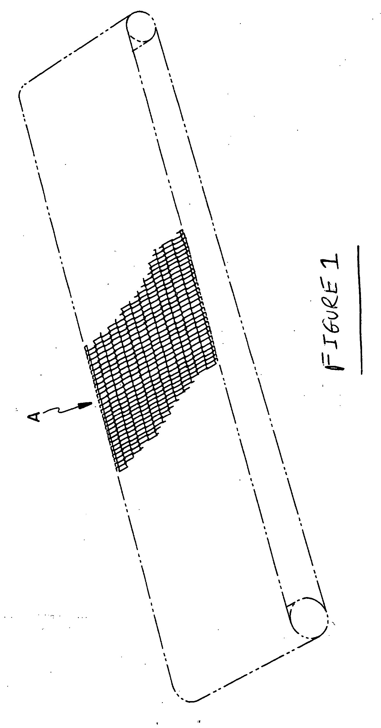
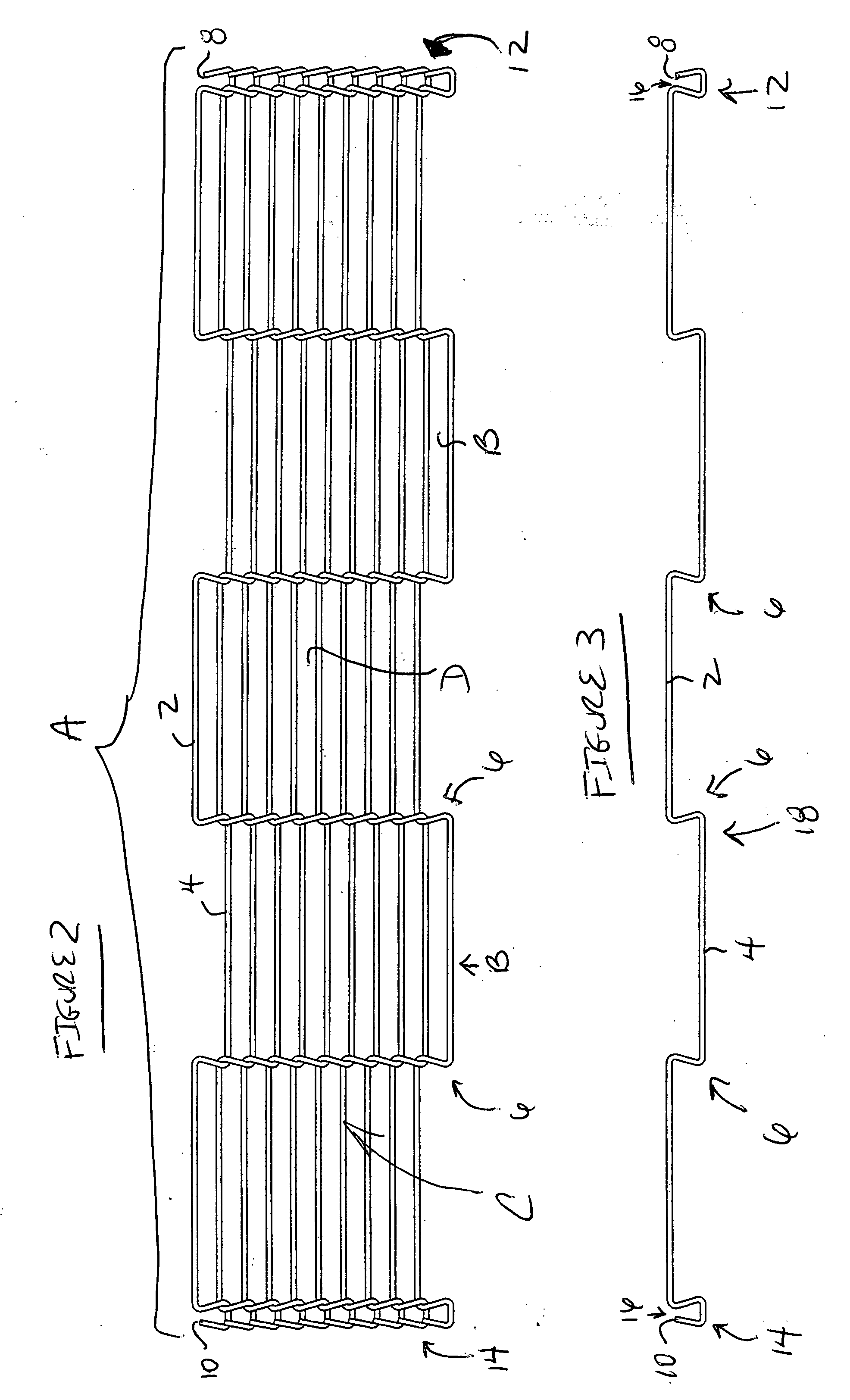
[0022] The most preferred form of the invention will now be described with reference to FIGS. 1-6. The appended claims are not limited to the most preferred embodiment and no term and / or phrase used herein is to be given a meaning other than its ordinary meaning unless accompanied by a statement that the term and / or phrase “as used herein is defined as follows”. The phrase “open end regions” as used herein is defined as follows: an end region of a wire segment that has a gap or space at least equal to the diameter of an adjacent wire segment permitting but not requiring the wire segments to be interconnected subsequent to formation of the end region without altering the configuration of the end region. By way of example only, it is noted that the end regions depicted in FIGS. 4A, 4B, 5 and 6 of U.S. Pat. No. 5,404,998 are not open end regions. The term “continuous” as used herein is defined as follows: free from a gap or space when viewed from a plan view perspective.

FIGS. 1 Throug...


PUM


Abstract

A conveyor belt including a plurality of interconnected wire segments forming a conveying surface to convey at least one article from one point to another. The conveying surface has first and second outermost edges. Preferably, each of the plurality of wire segments has open end regions permitting interlocking of adjacent wire elements without subsequent forming or reforming of the end regions. The outermost edges of the conveyor belt are formed to reduce the likelihood of snagging and / or injury.

Description

FIELD OF THE INVENTION [0001] The present invention is directed to devices used to convey objects from one location to another. In its most preferred form, the present invention is directed to an endless conveyor belt and a splicing member for forming the endless conveyor belt. BACKGROUND OF THE INVENTION [0002] Endless conveyor belts have been widely used to transport a number of different objects from one location to another. For example, endless conveyor belts have been used in the food processing industry to transport food products such as poultry, seafood, vegetables, cookies, crackers, bagels, tortillas and red meat. Typical food processes in which endless conveyor belts have been used include breading, battering, forming, frying, cooking, coating and baking. Endless conveyor belts have also been used in the food service industry to transport food products such as pizza, seafood, lunchmeat and toast. Endless conveyor belts can be found in this industry in impingement ovens in ...

Claims


Application Information

Patent Timeline
Patent Type & Authority Applications(United States)
IPC IPC(8): B65G15/54
CPCB65G15/54
Inventor FARRELL, GLENN PETER
Owner LUMSDEN FLEXX FLOW
Why Eureka
Try Eureka