Imaging module

Inactive Publication Date: 2006-11-30
DENSO CORP
View PDF6 Cites 34 Cited by
  • Summary
  • Abstract
  • Description
  • Claims
  • Application Information

AI Technical Summary

Benefits of technology

[0025] Usually, obstacles ahead of the vehicle concerned include, for example, vehicles existing in the vicinity of the vehicle, a tunnel and a bridge existing ahead of the vehicle, rain drops attached on the front window of the vehicle, and the like. When detecting these obstacles, the image information has to be taken in with sufficiently high resolution to perform predetermined image processing, such as recognition of its outer shape, without distortion. On the other hand, for detecting the illuminance around the vehicle concerned properly, image information of an image has to be taken in with a wider angle of view. Regarding this respect, according to the above-mentioned configuration as an imaging module, the obstacle ahead of the vehicle concerned are detected based on the light images formed on the imager correspondingly to the careful looking region, and the illuminance around the vehicl

Problems solved by technology

Accordingly, when the imaging elements are arranged over the whole surface of the imager with high density, imaging targets in the distance that do not need high resolution will be imaged with resolution equivalent to the careful looking region, which eventually results in the increase of a processing load on the image processor 152 for performing the image processing.
However, since the shields 140 limit the magnitude of the angle of view θ1 in the above-mentioned conventional imaging module, it is difficult to set the angle of view θ1 larger in order to meet such a requirement.
Further, when such reduction in the contrast is tried to be compensat

Method used


Image

  • Imaging module
  • Imaging module
  • Imaging module

Examples


first embodiment

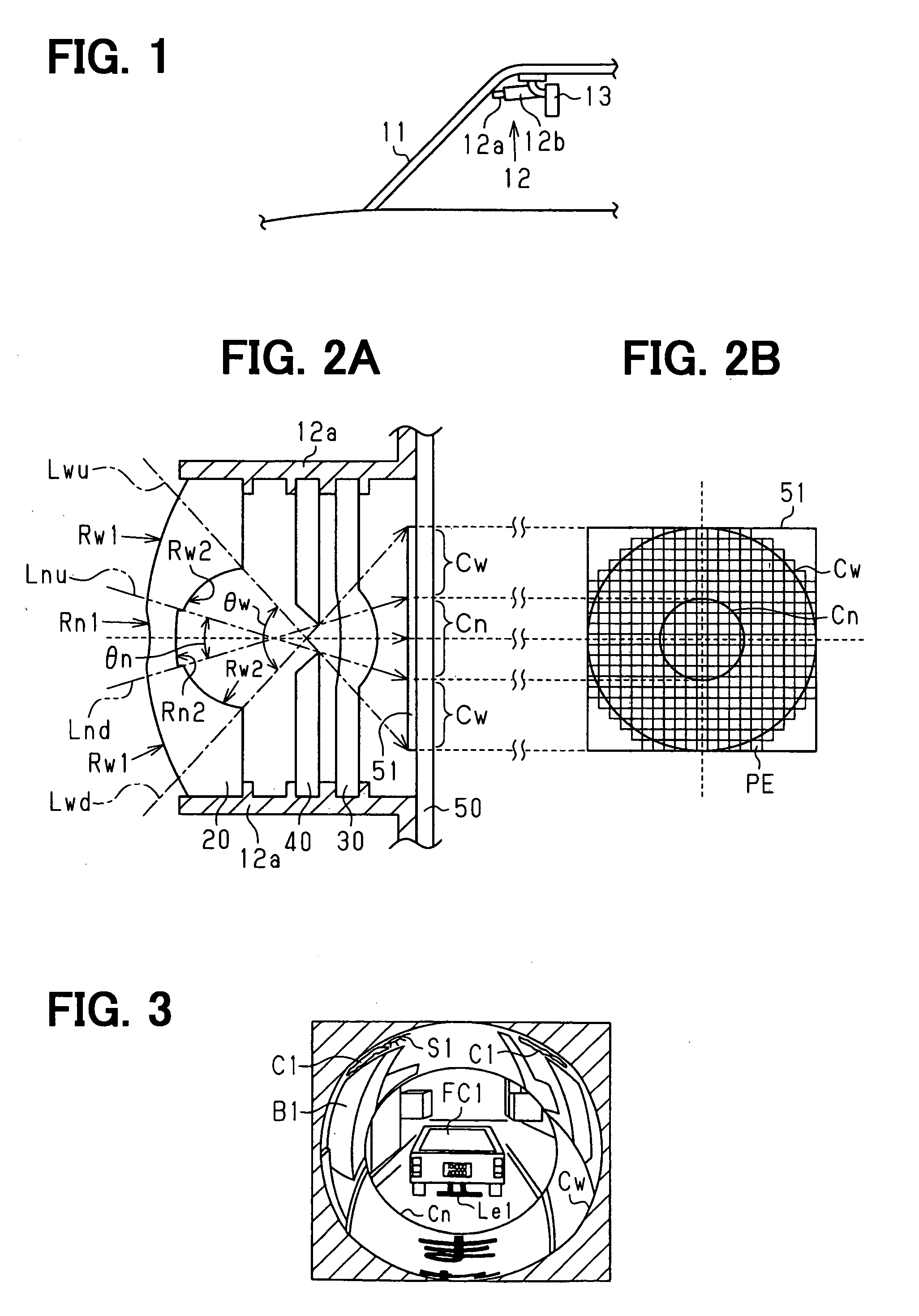
[0046] Hereafter, a first embodiment of an imaging module concerned with this invention will be described with reference to FIGS. 1 to 3.

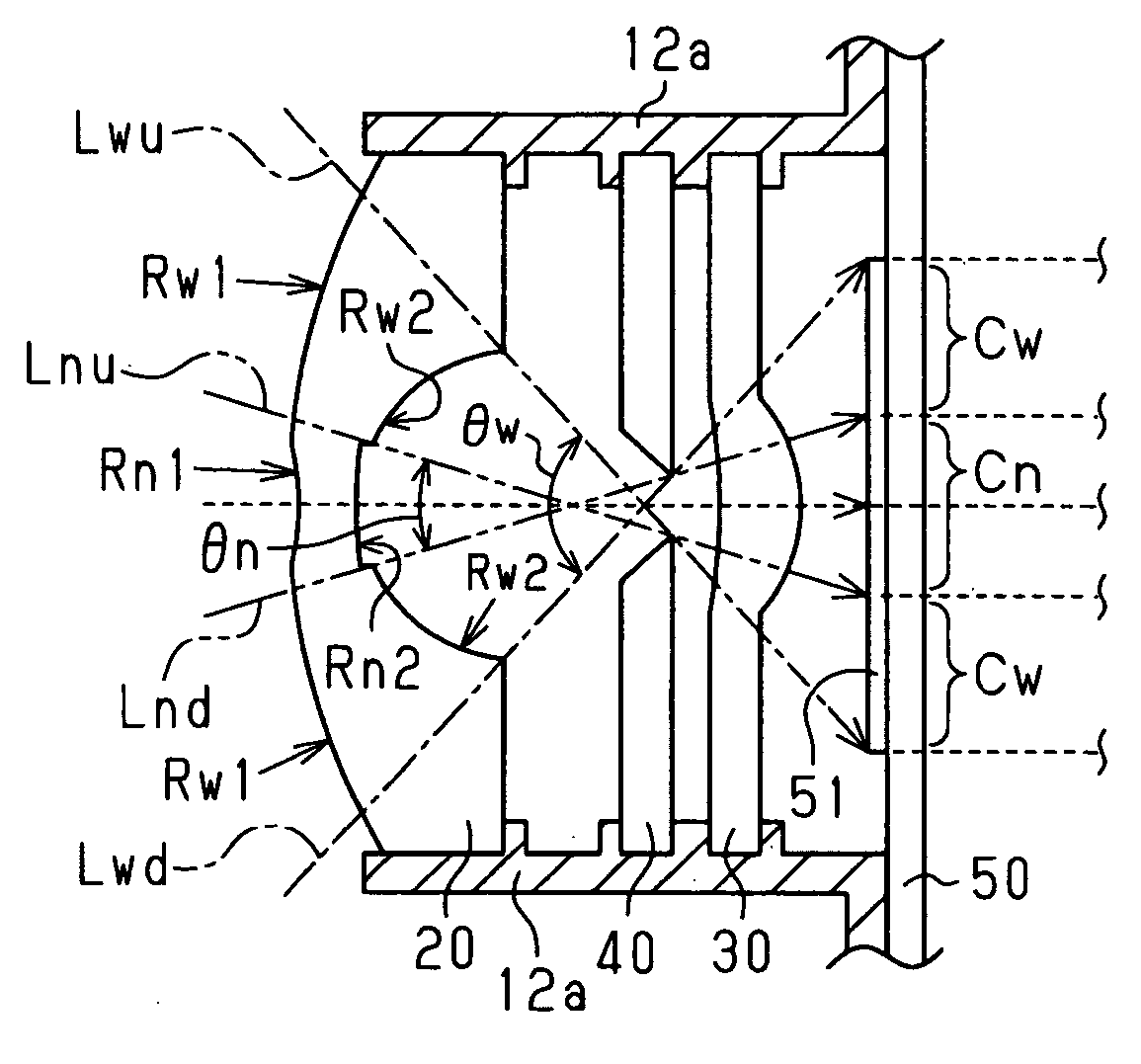
[0047] In this embodiment, as will be described in detail below, as an optical system for forming two kinds of light images, a light image of the careful looking region and that of its surrounding region, a fish-eye lens and a convex lens for converging to form the light images having passed through the fish-eye lens on the imager are arranged inside the lens-barrel, more specifically, the two lenses are arranged along the cylinder direction. Then, this fish-eye lens is formed in such a way that the sectional radius of curvature of its central part is smaller than the sectional radius of curvature of the peripheral part, whereby suitable compatibility between imaging characteristics required for the careful looking region and for its surrounding region, respectively, is intended to be achieved.

[0048]FIG. 1 shows one example of how the imaging sys...

second embodiment

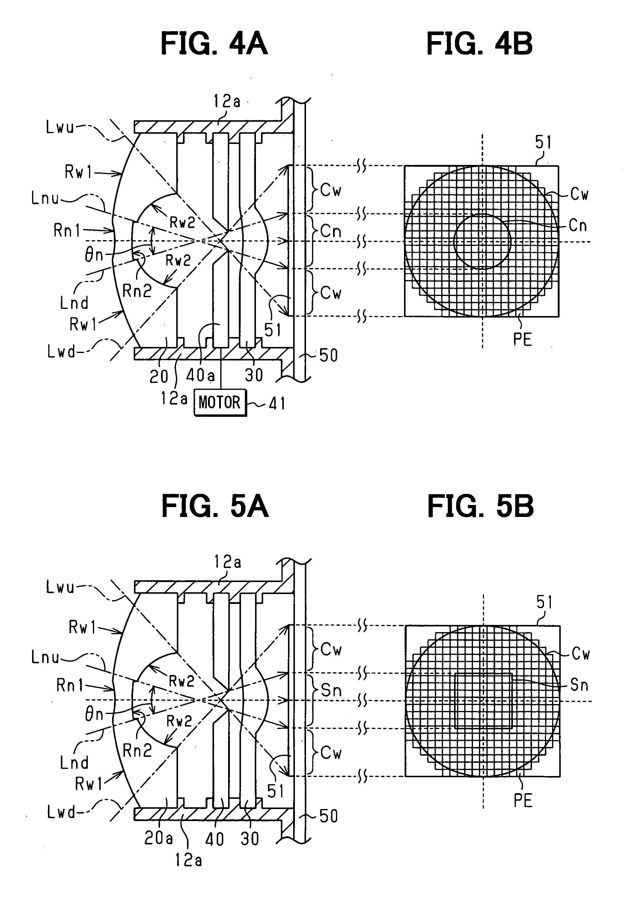
[0066] Next, a second embodiment of the imaging module concerned with this invention will be described with reference to FIGS. 4A and 4B, focusing on several points different from the first embodiment. FIG. 4A shows an internal structure of this second embodiment viewed from the side direction; FIG. 4B schematically shows an imaging mode viewed from the front direction. In FIGS. 4A and 4B, the same constituents as constituents shown in FIGS. 1 to 3 are designated with the same reference numerals, respectively, and redundant explanations of these constituents will be omitted.

[0067] As shown in FIGS. 4A and 4B, the imaging module of this embodiment has a configuration equivalent to the first embodiment shown in FIGS. 1 to 3. Note that, in this embodiment, the optical system is designed to be equipped with an auto iris 40 for automatically adjusting the amount of incident light on the convex lens, interposed between the fish-eye lens 20 and the convex lens 30, according to variation i...

third embodiment

[0072] Next, a third embodiment of the imaging module concerned with this invention will be described with reference to FIGS. 5A and 5B, focusing on several points different from the first embodiment. FIG. 5A shows an internal structure of this third embodiment viewed from the side direction; FIG. 5B schematically shows an imaging mode on the imager viewed from the front direction.

[0073] As shown in FIGS. 5A and 5B, the imaging module of this embodiment has a configuration equivalent to the first embodiment shown in FIGS. 1 to 3. Note that, in this embodiment, as shown in FIGS. 5A and 5B, the area where the sectional radius of curvature of the fish-eye lens 20a is formed smaller than the sectional radius of curvature of the peripheral part other than the area concerned is formed in the shape of a rectangle when viewed from the front.

[0074] According to this third embodiment of the imaging module explained above, effects as will be described below can newly be acquired, in addition...


PUM


Abstract

An imaging module having an imager comprised of a group of imaging elements arrayed in a square lattice and an optical system for forming two kinds of light images, a light image of a careful looking region and a light image of a surrounding region, on the imager in a lens-barrel. The optical system of the imaging module includes a plurality of lenses arranged in a cylinder direction of the lens-barrel, and one of the lenses is formed as an aspherical lens such that a sectional radius of curvature of a center part of the lens is smaller than the sectional radius of curvature of a peripheral part of the lens.

Description

CROSS REFERENCE TO RELATED APPLICATION [0001] This application is based on and claims the benefit of priority of Japanese Patent Application No. 2005-154337 filed on May 26, 2005, the disclosure of which are incorporated herein by reference. FIELD OF THE INVENTION [0002] This invention relates to an imaging module that is carried on board, for example, a vehicle and forms light images of a plurality of objects that should be imaged (hereinafter referred to as an imaging target) on an imager, intending to detect vehicles existing in the vicinity of the vehicle concerned or the illuminance around the vehicle, and the like. BACKGROUND OF THE INVENTION [0003] Conventionally, an imaging system having an imaging module is used, for example, for imaging objects around a vehicle. The imaging system disclosed in Japanese Patent document JP-A-2004-158017 is one of the examples. The outline of the imaging module is shown in FIGS. 10 to 12 based on the description of the disclosure. [0004] As s...

Claims


Application Information

Patent Timeline
IPC IPC(8): G06K7/10G02B7/02G03B9/02H04N5/225H04N5/232H04N5/238H04N5/335H04N5/376
CPCB60R11/04H04N5/2259H04N5/2254G02B13/16H04N23/58H04N23/55H04N23/63H04N23/75
Inventor TANIDA, KATSUNORI
Owner DENSO CORP
Why Eureka
Try Eureka