
Cross-flow fan propulsion system

Active Publication Date: 2006-11-30
SYRACUSE UNIVERSITY
View PDF10 Cites 20 Cited by
  • Summary
  • Abstract
  • Description
  • Claims
  • Application Information

AI Technical Summary

Benefits of technology

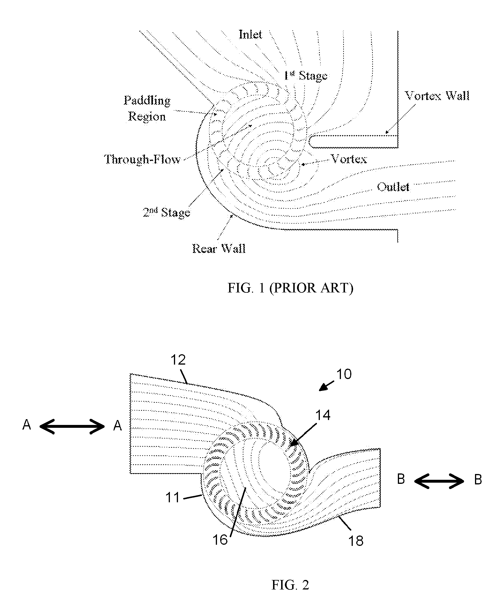
[0009] It is therefore a principal object and advantage of the present invention to provide a distributed cross-flow fan wing design that provides high propulsive efficiency.
[0010] It is a further object and advantage of the present invention to provide a distributed cross-flow fan wing design that provides low parasite drag.
[0011] It is an additional object and advantage of the present invention to provide a distributed cross-flow fan wing design that provides reduced flow separation at high angle of attack.
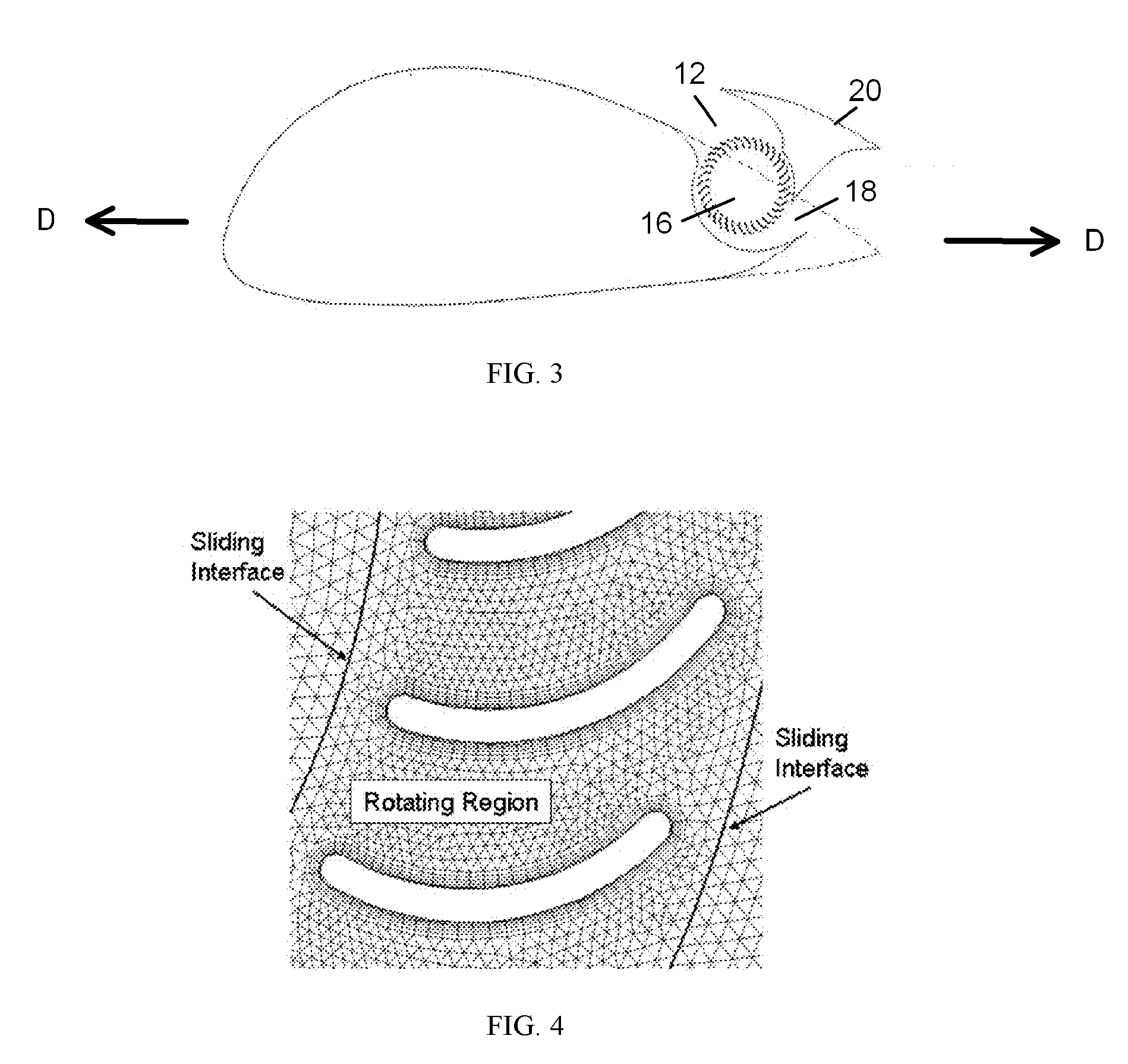
[0012] In accordance with the foregoing objects and advantages, in one application, the present invention provides a cross-flow propulsion mechanism for use in providing propulsion to an aircraft, that includes a housing defining an inlet, a rotor compartment, and an outlet, with the inlet adapted to receive an inflow of air along a first longitudinal axis; a rotor mounted within the rotor compartment and adapted to receive the airflow introduced into said housing through the inlet and rotate about a second longitudinal axis that is substantially perpendicular to the first longitudinal axis; and an outlet adapted to receive the airflow processed through the rotor and exhaust air along a third longitudinal axis that is substantially parallel to the first longitudinal axis.
[0013] In a second application of the invention, it provides an aircraft including an aircraft body shaped in the form of an airfoil having leading and trailing edges; and a cross-flow propulsion mechanism for use in providing propulsion to an aircraft, that includes a housing defining an inlet, a rotor compartment, and an outlet, with the inlet adapted to receive an inflow of air along a first longitudinal axis; a rotor mounted within the rotor compartment and adapted to receive the airflow introduced into said housing through the inlet and rotate about a second longitudinal axis that is substantially perpendicular to the first longitudinal axis; and an outlet adapted to receive the airflow processed through the rotor and exhaust air along a third longitudinal axis that is substantially parallel to the first longitudinal axis.
[0014] In a third application of the present invention, it provides a vehicle convertible between land travel and air travel, that includes a vehicle body shaped in the form of an airfoil having leading and trailing edges; and a cross-flow propulsion mechanism for use in providing propulsion to an aircraft, that includes a housing defining an inlet, a rotor compartment, and an outlet, with the inlet adapted to receive an inflow of air along a first longitudinal axis; a rotor mounted within the rotor compartment and adapted to receive the airflow introduced into said housing through the inlet and rotate about a second longitudinal axis that is substantially perpendicular to the first longitudinal axis; and an outlet adapted to receive the airflow processed through the rotor and exhaust air along a third longitudinal axis that is substantially parallel to the first longitudinal axis.

Problems solved by technology

The conventional HVAC-type CFF housing, characterized by approximately a 90 degree turn from inlet to outlet, is not well suited for this application
These regions are dissipative, and as a result, only a portion of the impeller imparts useable work on the flow.
Attempts to provide a cross-flow fan in aircraft wings haven been unsuccessful.
These designs, however, limits the fan size and ducting.
Also, the CFF may not be a viable option for high-speed applications due to compressibility effects (i.e. choking).
These configurations fall short of expectations due to poor fan placement and poor housing design.
These deficiencies result in low fan performance, reduced circulation control, and low thrust production.

Method used


Image

  • Cross-flow fan propulsion system
  • Cross-flow fan propulsion system
  • Cross-flow fan propulsion system

Examples


Embodiment Construction

[0039] Glossary:

[0040] A=area

[0041] CD=airfoil drag coefficient, D / (0.5 ρU∞2C)

[0042] CL=airfoil lift coefficient, L / (0.5 ρU∞2C)

[0043] CP=power coefficient, Power / (ρU∞3Df)

[0044] CT=thrust coefficient, T / (0.5 ρU∞2Df)

[0045] CS=control surface

[0046] D=drag per unit span

[0047] DBL=drag due to boundary layer build-up

[0048] Df=cross-flow fan diameter

[0049] Fx=x-component of force

[0050] H=arbitrarily large distance

[0051] hi=propulsor inlet height

[0052] hj=propulsor outlet height

[0053] hw=ingested wake height

[0054] {tilde over (h)}=non-dimensionalized ingested wake height

[0055] L=lift per unit span

[0056] {dot over (m)}=mass flow rate

[0057] p=variable

[0058] PP=propulsive power

[0059] PT=total pressure

[0060] PTi=total pressure at propulsor inlet

[0061] {overscore (PTi)}=mass-weighted total pressure at propulsor inlet

[0062] Q=flow rate per unit span

[0063] r=radial distance

[0064] T=propulsor thrust

[0065] U=velocity

[0066] Uf=fan tip speed

[0067]Ũj=non-dimensionalized jet ...


PUM


Abstract

A cross-flow propulsion mechanism for use in providing propulsion to an aircraft, includes a housing defining an inlet, a rotor compartment, and an outlet. The inlet is adapted to receive an inflow of air along a first longitudinal axis. The rotor is mounted within the rotor compartment and adapted to receive the airflow introduced into said housing through the inlet and rotate about a second longitudinal axis that is substantially perpendicular to the first longitudinal axis. The outlet is adapted to receive the airflow processed through the rotor and exhaust air along a third longitudinal axis that is substantially parallel to the first longitudinal axis. The propulsion mechanism can be applied in a personal aircraft, an STOL aircraft, and a hybrid automobile and aircraft.

Description

PRIORITY CLAIM [0001] This application claims priority to U.S. Provisional Patent Application Ser. No. 60 / 673,541, filed Mar. 21, 2005, U.S. Provisional Patent Application Ser. No. 60 / 673,624, filed Mar. 21, 2005 and U.S. Provisional Patent Application Ser. No. 60 / 673,552, filed Mar. 21, 2005.BACKGROUND OF THE INVENTION [0002] 1. Field of the Invention [0003] The present invention relates to aircraft propulsion systems and, more specifically, a cross-flow fan propulsion system. [0004] 2. Description of the Prior Art [0005] The cross-flow fan (CFF), developed in 1893 by Mortier, is used extensively in the HVAC industry. The fan is usually long in relation to the diameter, so the flow approximately remains 2-dimensional (2D). The CFF uses an impeller with forward curved blades, placed in a housing consisting of a rear wall and vortex wall. Unlike radial machines, the main flow moves transversely across the impeller, passing the blading twice. FIG. 1 shows a typical heating, ventilatio...

Claims


Application Information

Patent Timeline
IPC IPC(8): B64D27/00
CPCB64C3/141B64C11/006B64C21/06B64C23/02B64C39/005B64C2003/143B64C2230/04B64C2039/105B64D27/02Y02T50/12Y02T50/166B64C2230/06B64C2003/147Y02T50/10B64C21/01
Inventor KUMMER, JOSEPH D.DANG, THONG Q.
Owner SYRACUSE UNIVERSITY
Learn More