RFID-tag fabricating apparatus and cartridge

a technology of fabricating apparatus and printed labels, which is applied in the direction of identification means, instruments, paper/cardboard articles, etc., can solve the problems of difficulty in visual inspection of printed characters, limitation of area, and conventional techniques indicated above do not take into account the relationship between the dimensions of rfid tags and the dimensions of printed indicia formed on printed labels, so as to achieve easy visible

Active Publication Date: 2006-11-30
BROTHER KOGYO KK
View PDF20 Cites 38 Cited by
  • Summary
  • Abstract
  • Description
  • Claims
  • Application Information

AI Technical Summary

Benefits of technology

[0015] In a preferred form of the first and second aspects of this invention, the second substrate is bonded at one of its opposite surfaces to the first substrate, and includes an adhesive layer and a releasing layer formed on the other of its opposite surfaces. In this case, the fabricated RFID tag can be easily affixed to a desired article such as an article of commodity, by the adhesive layer which is exposed by removing the releasing layer.
[0029] In a still further preferred form of the invention, the substrate-accommodating device further accommodates an intermediate substrate to be inserted between the first substrate and the circuit substrate. In this form of the invention, the IC circuit portions are suitably protected, and a printed indicium formed on the first substrate is easily visible, by selecting the color of the intermediate substrate depending upon the color of the printed indicium.

Problems solved by technology

The conventional RFID tags are dimensioned without a special consideration of formation of the printed indicium, so that there is a limitation in the size of the area in which the combination of characters, bar code or any other printed indicium is formed.
Where a relatively large number of characters are printed on the RFID tag, the maximum size of each character is limited, with a result of undesirable difficulty of visual inspection of the printed characters.
However, the conventional techniques indicated above do not take into account a relationship between the dimensions of the RFID tags and those of the printed indicia formed on the printed labels.
Therefore, the conventional techniques do not solve the problem.
Thus, there is not available any technique by which the dimensions of the RFID tags can be changed depending upon the dimensions of the printed indicium to be formed on each RFID tag.

Method used


Image

  • RFID-tag fabricating apparatus and cartridge
  • RFID-tag fabricating apparatus and cartridge
  • RFID-tag fabricating apparatus and cartridge

Examples


first embodiment

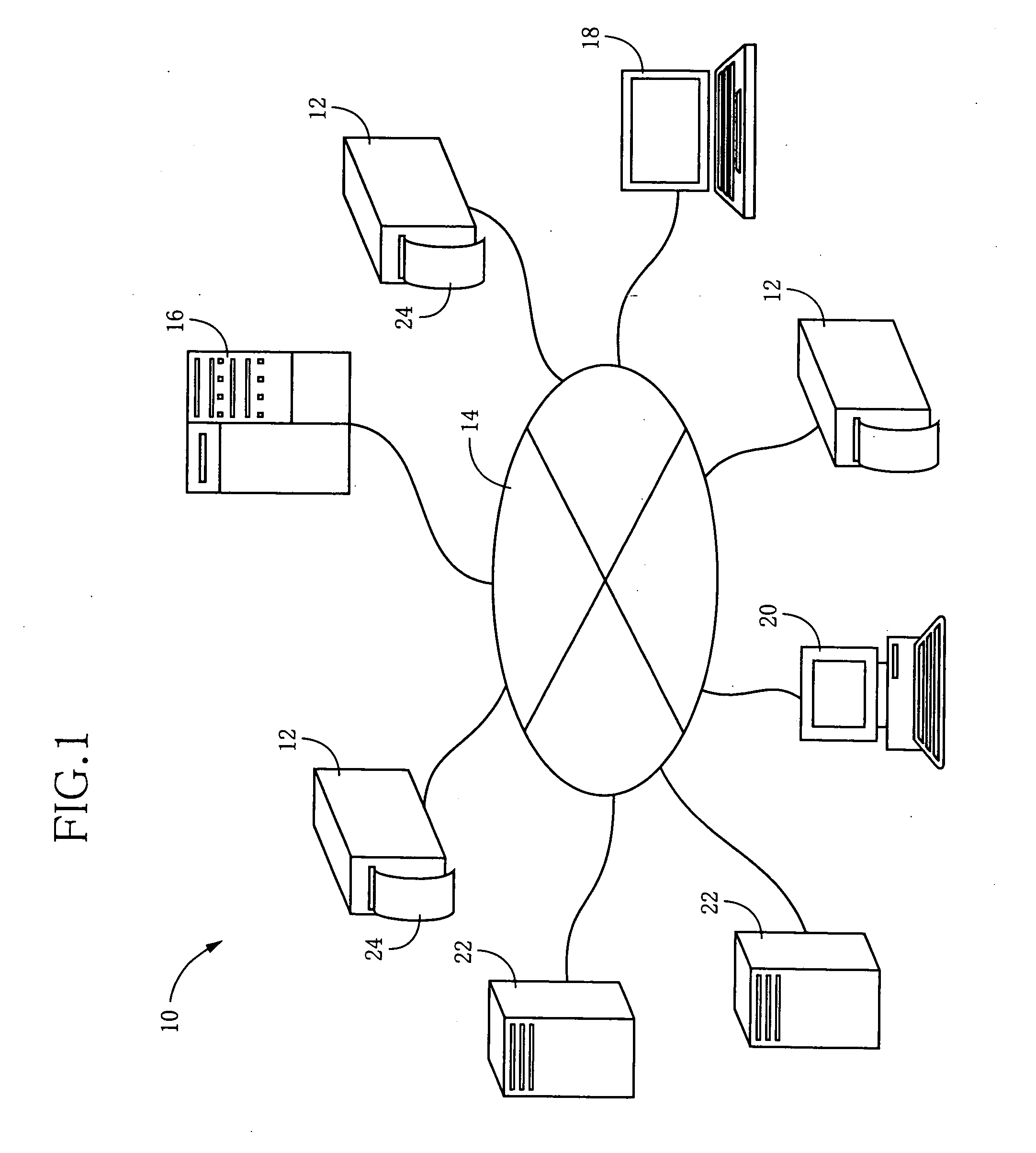
[0105] Referring to FIG. 1, there is illustrated an RFID system 10 to which the present is suitably applicable. In this RFID system 10, a plurality of RFID-tag fabricating apparatuses 12 each constructed according to the present invention are connected to a route server 16, a terminal 18, a general-purpose computer 20, and a plurality of information servers 22, through a wire (cable) or wireless communication line 14.

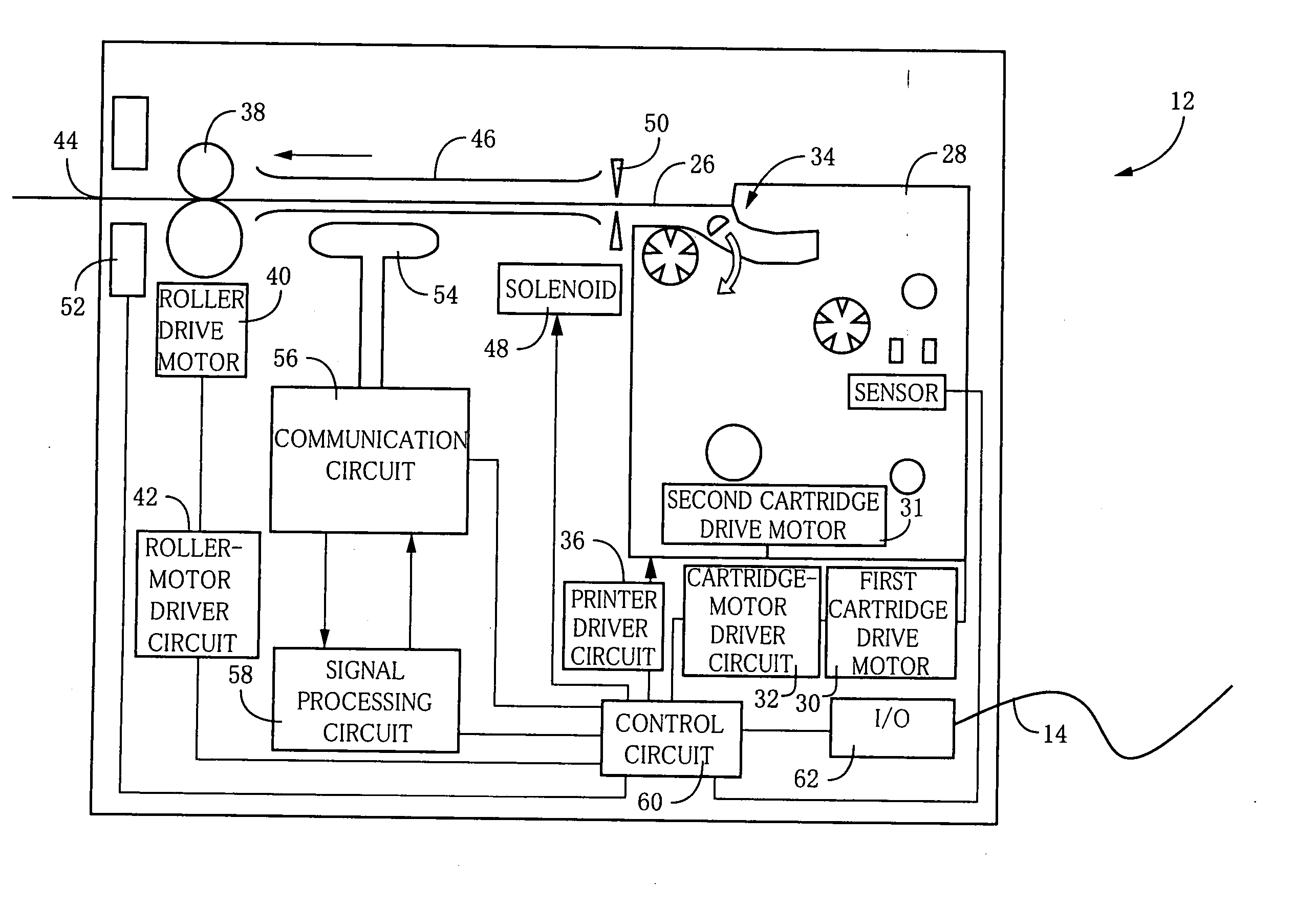
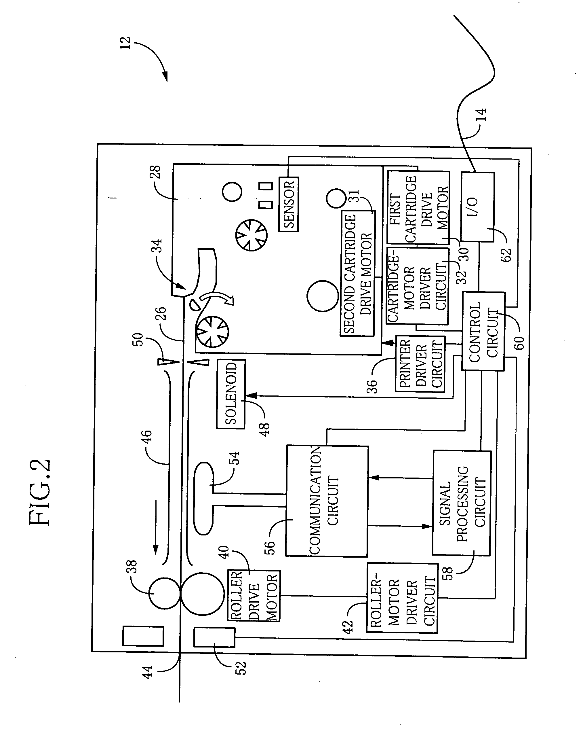
[0106] Referring to FIG. 2, there is shown an arrangement of the above-described RFID-tag fabricating apparatus 12 constructed according to a first embodiment of this invention. This RFID-tag fabricating apparatus 12 is arranged to produce RFID tags 24 shown in FIGS. 4 and 15-23, in an instant, so as to meet a need of the user. For example, each RFID tag 24 is provided with desired writing ID, commodity information and other information stored in an IC circuit portion 66, as described below. As shown in FIG. 2, the RFID-tag fabricating apparatus 12 includes a removably...

second embodiment

[0156] Other embodiments of this invention will be described by reference to FIGS. 45-73 wherein the reference signs used in the first embodiment will be used to identify the same elements in the following embodiments, which will not be described.

[0157] Referring to FIG. 45, there is shown an arrangement of a cartridge 160 used in a second embodiment of this invention. This cartridge 160 accommodates a first substrate 80 shown in the cross sectional view of FIG. 46, a circuit substrate 162 shown in the cross sectional view of FIG. 47, and a second substrate 82 shown in the cross sectional view of FIG. 48. The circuit substrate 162 takes the form of a third roll 164 of a tape which carries a multiplicity of RFID tag circuits 24A successively arranged at a predetermined pitch on a base film 112 in its longitudinal direction. The circuit substrate 162 has half cuts 118 or lines of perforations 120 formed successively in the longitudinal direction at a predetermined spacing pitch, so t...

third embodiment

[0160] Referring to FIG. 49, there is shown an arrangement of a cartridge 170 used in a third embodiment of this invention. This cartridge 170 accommodates a first substrate 80 shown in the cross sectional view of FIG. 50, an intermediate substrate 176 shown in the cross sectional view of FIG. 51, a circuit substrate 172 consisting of planar elements 173 shown in the cross sectional view of FIG. 52, and a second substrate 82 shown in the cross sectional view of FIG. 53. The circuit substrate 172 takes the form of a third roll 174 including the releasing layer 116 to which a multiplicity of planar elements 173 in the form of strips are bonded through adhesive layers formed on their back surfaces, such that the planar elements 173 are successively arranged in the longitudinal direction of the releasing layer 116. Each of those elements 173 of the circuit substrate 172 carries one RFID tag circuit 24A fixed to the base film 112. The releasing layer 116 carrying the elements 173 is woun...


PUM

PropertyMeasurementUnit
lengthaaaaaaaaaa
coloraaaaaaaaaa
colorsaaaaaaaaaa

Abstract

An RFID-tag fabricating apparatus for fabricating an RFID tag provided with an IC circuit, including a substrate-accommodating device for accommodating a first substrate in the form of a tape having a printable surface and a second substrate in the form of a tape to be bonded to the first substrate, a printing device operable to form a predetermined printed indicium on the printable surface of the first substrate, a tag-tape forming device operable to form a tag tape, by bonding together the first and second substrates such that a plurality of IC circuit portions are interposed between the first and second substrates, a tag-tape cutting device operable to cut the tag tape formed by the tag-tape forming device, and a tag-tape cutting control portion operable to change a length of a segment of the tag tape to be obtained as the RFID tag by cutting of the tag tape by the tag-tape cutting device, on the basis of a length of the printed indicium formed on the first substrate, and such that the segment includes at least one of the IC circuit portions, whereby the dimensions of the RFID tag can be changed depending upon the dimensions of the printed indicium formed on the first substrate.

Description

[0001] The present application is a continuation-in-part of International Application No. PCT / JP2004 / 017020 filed Nov. 16, 2004; which claims the benefits of Japanese Patent Application No. 2003-394346 filed Nov. 25, 2003. BACKGROUND OF THE INVENTION [0002] 1. Field of the Invention [0003] The present invention relates to an RFID-tag fabricating apparatus arranged to write information on or read information from radio or wireless tags (RFID tags) on and from which information can be read or written by radio communication, and a cartridge removably mounted on the RFID-tag fabricating apparatus. [0004] 2. Description of the Related Art [0005] There is known an RFID (Radio Frequency Identification) system wherein a reader or interrogator is operable in a non-contact fashion to read information from small-sized RFID tags or transponders which store desired information. This RFID system permits the information stored in the RFID tags, to be read by the reader by radio communication even ...

Claims


Application Information

Patent Timeline
Patent Type & Authority Applications(United States)
IPC IPC(8): G08B13/14B42D15/10B31D1/02B65C11/02G06K17/00G06K19/07G06K19/077G09F3/00
CPCB31D1/021B31D1/027B65C11/02B65C2009/0003B65C2210/0097Y10T428/12556B31D1/028Y10T156/1054Y10T428/14Y10T156/1089Y10T156/1093G06K19/07749
Inventor TAKI, KAZUNARIYASUI, KUNIHIROSUGIYAMA, KOJITANAKA, MITSUGIUCHIGASHIMA, HIROSHITAKITO, KOJI
Owner BROTHER KOGYO KK
Why Eureka
Try Eureka