
Imaging device and method, computer program product on computer-readable medium, and imaging system

a computer-readable medium and imaging system technology, applied in the field of imaging devices and methods, can solve the problems of inability to find such changes of scenes, difficult to find such intruders, and inability to know the details of intrusions, and achieve the effect of high-accuracy surveillan

Inactive Publication Date: 2006-11-30
SONY CORP
View PDF11 Cites 22 Cited by
  • Summary
  • Abstract
  • Description
  • Claims
  • Application Information

AI Technical Summary

Benefits of technology

[0036] According to the present invention, a moving subject in a surveillance area is detected based on an infrared image signal acquired by imaging the area by infrared radiation measurement, a moving part of the infrared image signal is colored with a predetermined color and an image resulted from the coloring of the moving part of the infrared image signal is displayed. Thus, a moving subject included in an infrared image of the surveillance area can be displayed in the color day and night and hence the moving subject in the surveillance area can also definitely be identified in a relation with its background. Also, since any slight movement of a person can be detected without fail, the present invention provides a higher-accuracy surveillance.

Problems solved by technology

Further, since the surveillance / monitoring system depends on the observer's eyes, he or she may possibly fail to find such changes of a scene.
Especially, in case the range of a scene under surveillance is wider, it is extremely difficult to find such an intruder.
Furthermore, since the image captured by the camera at night is so dark itself that it is not possible to know details of an intrusion, that is, from which part of which building a person has entered the off-limits area or through which route the intruder has moved.
The wider the range of a scene under surveillance, the more difficult it is to know the above details.
So, in case an object poor in variation of shape and temperature distribution is imaged, it is difficult in many cases to verify a target and scene around the target.

Method used


Image

  • Imaging device and method, computer program product on computer-readable medium, and imaging system
  • Imaging device and method, computer program product on computer-readable medium, and imaging system
  • Imaging device and method, computer program product on computer-readable medium, and imaging system

Examples


Embodiment Construction

[0046] The present invention will be described in detail below concerning embodiments thereof with reference to the accompanying drawings.

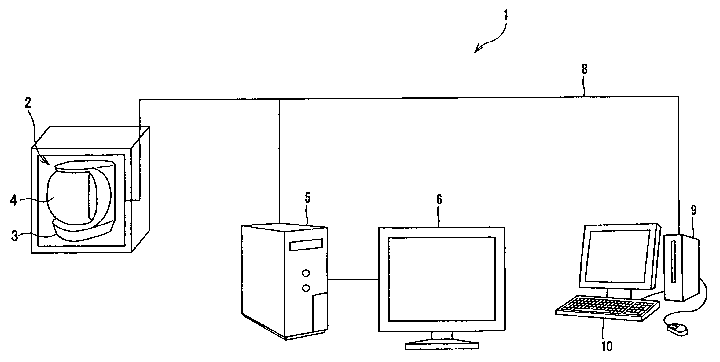
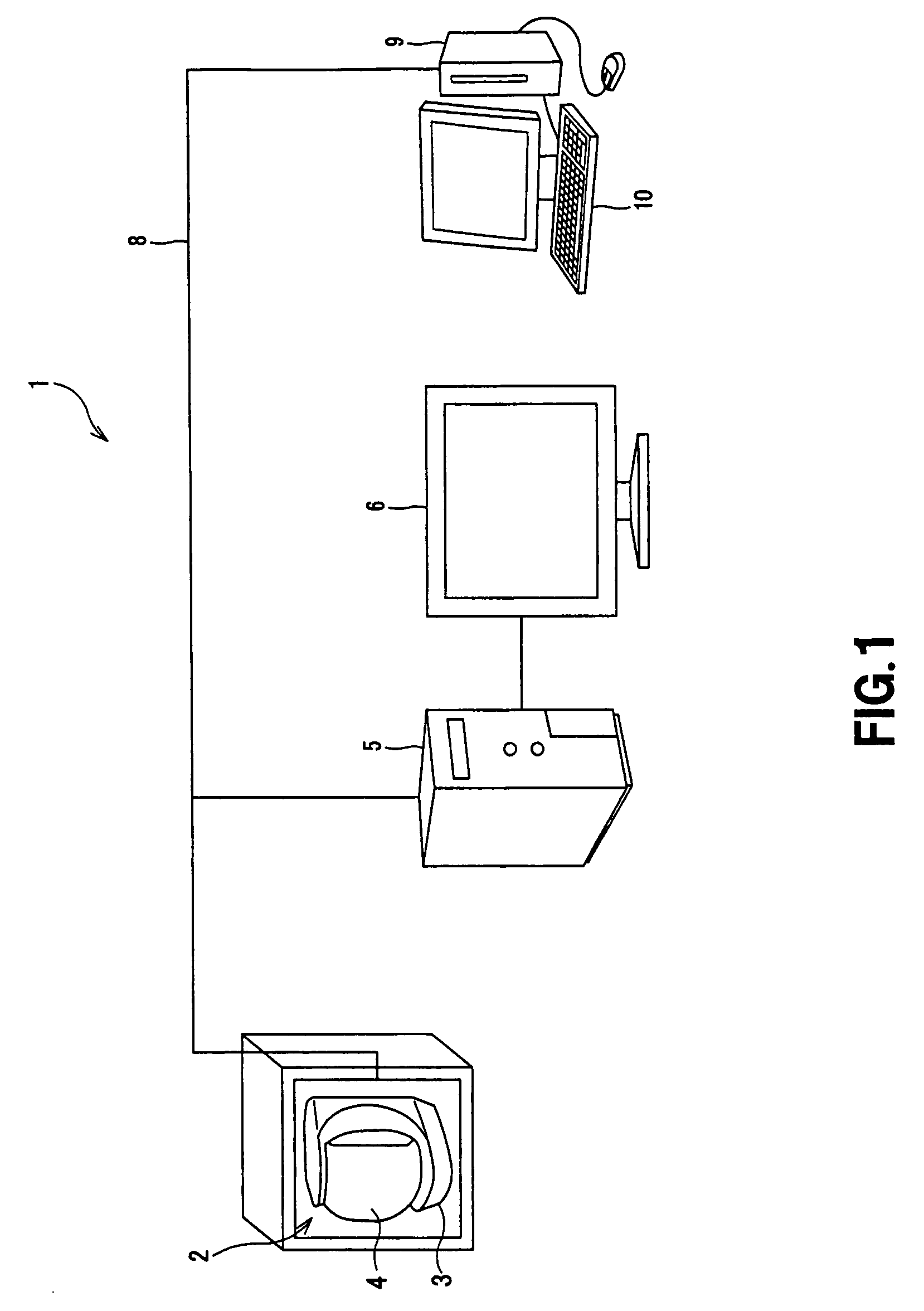
[0047] The present invention is applied to a surveillance / monitoring system 1 constructed as shown in FIG. 1, for example.

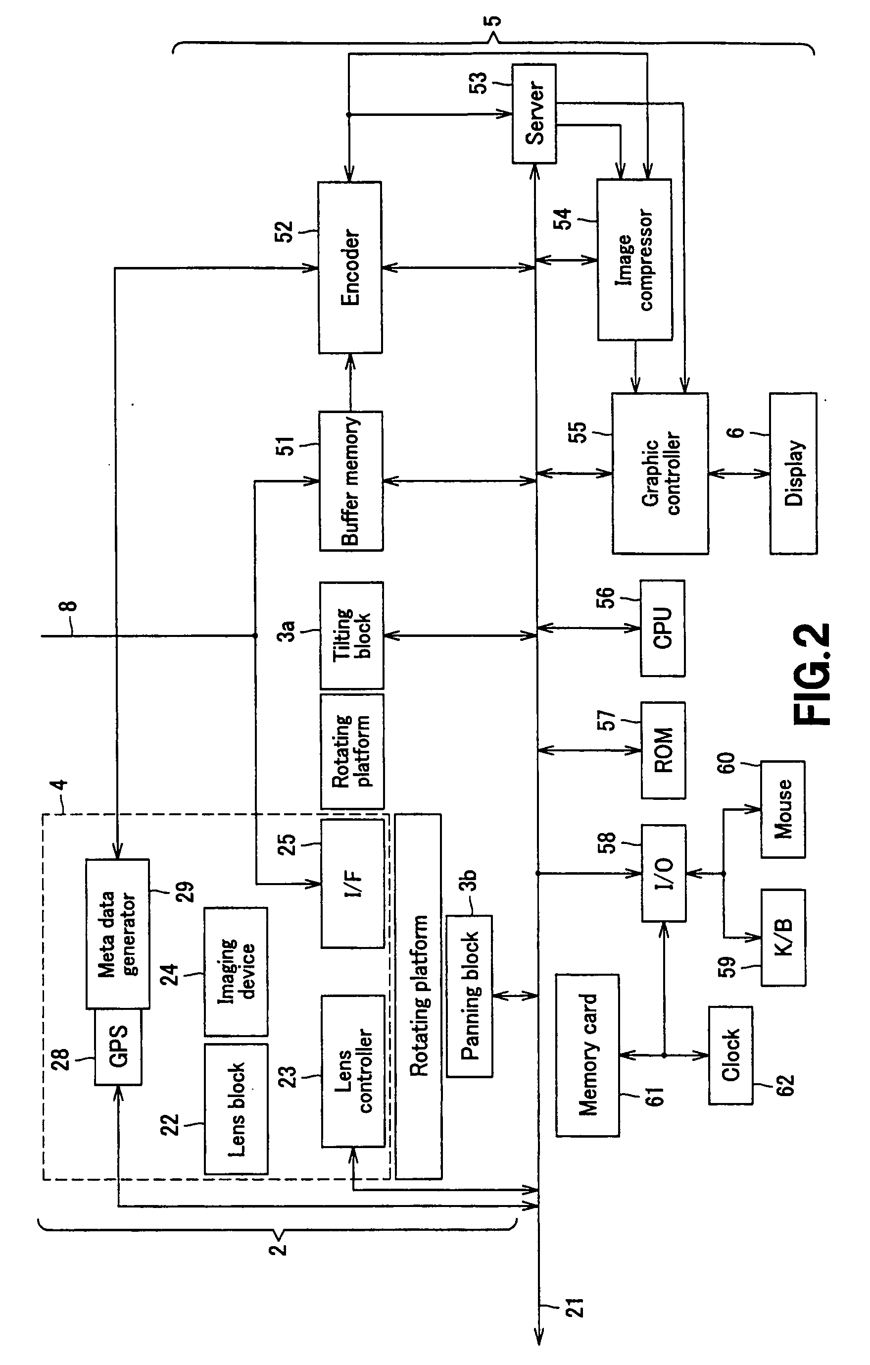
[0048] The surveillance / monitoring system 1 includes an infrared camera 2 to image an area under surveillance, monitor 5 supplied with an infrared image signal from the infrared camera 2, display 6 connected to the monitor 5, terminal unit 9 used by a plurality of users to execute their applications, terminal display 10 connected to the terminal unit 9, and a network 8 to make two-way communications among the infrared camera 2, monitor 5 and terminal unit 9.

[0049] Of the surveillance / monitoring system 1, the infrared camera 2 is an integration of a pan / tilter 3 and camera block 4. The pan / tilter 3 is formed as a rotating platform that can be turned about tilting and panning axes, for example, to freely shift the imaging dire...


PUM


Abstract

It is possible to definitely identify a relative position of a moving subject in an infrared image captured by an infrared camera in a relation with the background of the moving subject. The present invention provides an imaging device including an infrared camera for imaging an area under surveillance by infrared radiation measurement, a moving-subject detector for detecting a moving subject in the surveillance area on the basis of an infrared image signal acquired by the infrared camera, an image signal processor for coloring a moving part of the infrared image signal, detected by the moving-subject detector, with a predetermined color, and an image display for displaying an image resulted from the coloring of the moving part of the infrared image signal by the image signal processor.

Description

CROSS REFERENCES TO RELATED APPLICATIONS [0001] The present invention contains subject matter related to Japanese Patent Application JP 2005-154446 filed in the Japanese Patent Office on May 26, 2005, the entire content of which is incorporated herein by reference. BACKGROUND OF THE INVENTION [0002] 1. Field of the Invention [0003] The present invention relates to an imaging device and method, computer program product on a computer-readable medium and an imaging system, for surveillance of a wide-range scene by means of a panoramic image obtained by imaging with sequential shifting of the imaging direction. [0004] 2. Description of the Related Art [0005] In the electronic still cameras having been used widely in the past, light having passed through a lens by releasing the shutter of the camera to image an object can be converted into an image signal by a solid-state image sensor such as CCD (charge-coupled device) and the image signal be recorded to a recording medium. The image si...

Claims


Application Information

Patent Timeline
IPC IPC(8): H04N5/225H04N7/18H04N5/33H04N9/47
CPCG06T7/2053G06T11/60G08B13/19602G08B13/19691H04N5/33H04N5/23206H04N5/23238H04N5/23293H04N5/262H04N5/232G06T7/254H04N23/661H04N23/61H04N23/631H04N23/698H04N23/695H04N23/20
Inventor IKEDA, YUKIO
Owner SONY CORP
Learn More