Exposure method and apparatus

a technology of exposure method and apparatus, applied in the field of exposure method, can solve the problem of non-negligeable impact of errors on imaging performan

Inactive Publication Date: 2006-11-30
CANON KK
View PDF9 Cites 10 Cited by
  • Summary
  • Abstract
  • Description
  • Claims
  • Application Information

AI Technical Summary

Benefits of technology

[0006] The present invention is directed to an exposure method and apparatus that can precisely measure an actual device mask's flatness using a focus monitor mask.

Problems solved by technology

Because of such variation errors and other errors, a measurement result obtained by using a focus monitor mask (e.g., a scan field curvature) and the one obtained by using an actual device mask do not necessarily agree.
Further, due to a requirement for more minute devices, etc. in recent years, the impact of the errors on the imaging performance has become non-negligible.

Method used


Image

  • Exposure method and apparatus
  • Exposure method and apparatus
  • Exposure method and apparatus

Examples


Embodiment Construction

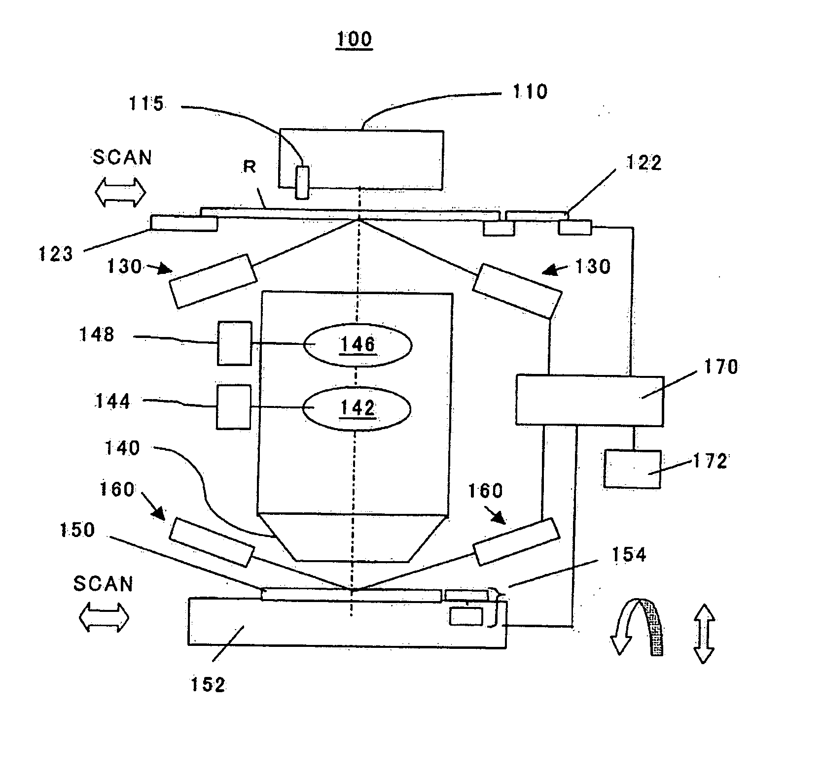
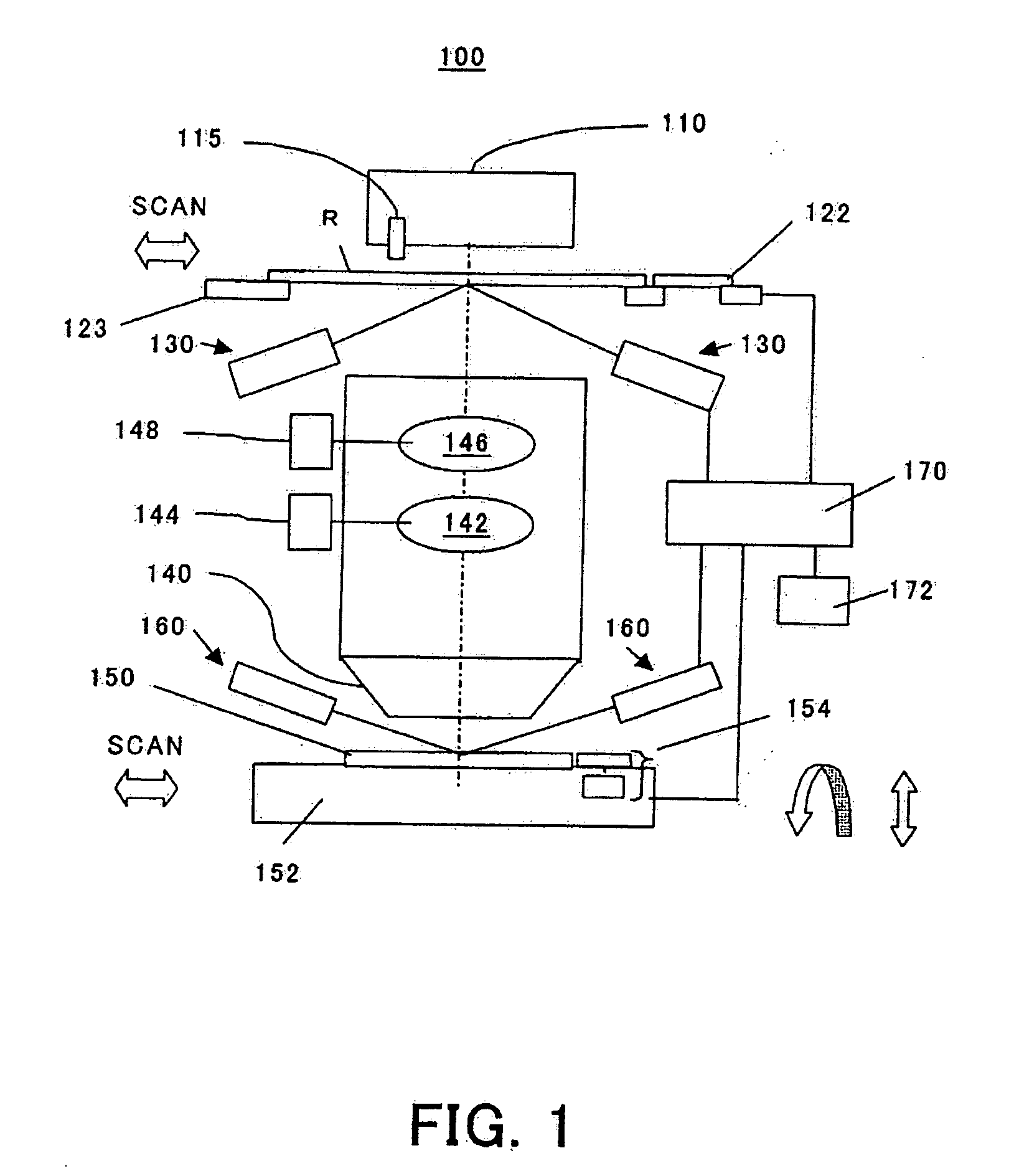
[0023] A description will now be given of an exposure method and apparatus as embodiments of this invention referring to accompanying drawings. Here, FIG. 1 is a schematic block diagram of an exposure apparatus 100. As shown in FIG. 1, the exposure apparatus 100 has an illumination apparatus 110, a mask stage 123, a projection optical system 140 and a wafer stage 152. Further, the exposure apparatus 100 also has a scope 115, a mask flatness measuring unit 130, a wafer surface position detector 160, a controller 170, and a memory 172.

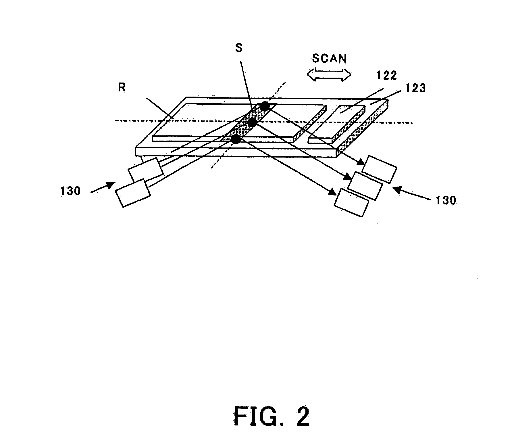
[0024] A mask R can be loaded (mounted) on the mask stage 123. As a mask R, various kinds of masks are available such as an actual device mask 120 and a focus monitor mask 124 described later. On the mask stage 123, there is provided a plane (reference surface) 122 as a basis for the flatness measuring unit 130.

[0025] A wafer 150 can be loaded on the wafer stage 152. A stage reference mark 154 is provided on the wafer stage 152.

[0026] The exposure app...


PUM


Abstract

An exposure method for an exposure apparatus that exposes a mask pattern onto a plate using a projection optical system includes the steps of obtaining information about flatness of a first mask, condition of an image plane when projecting a pattern of the first mask by using the projection optical system, information about a driving amount of a driving system, which can change an imaging condition on the plate based on the condition of the image plane, and information about flatness of a second mask, changing information about the driving amount by using information about flatness of the first and second masks, and driving the driving system based on changed information about the driving amount of the driving system to project a pattern of the second mask onto the plate using the projection optical system.

Description

BACKGROUND OF THE INVENTION [0001] The present invention relates generally to an exposure method, and more particularly to a measurement of a change in shape of a mask (or a reticle) on which a pattern is formed that is transferred to a plate via a projection optical system. The exposure method and apparatus of this invention is suitable for an exposure method and apparatus that corrects an aberration in a projection optical system and a focus position based on information about mask's flatness. [0002] In manufacturing a semiconductor device and the like using a photo-lithography process, a projection exposure apparatus has been used that transfers a pattern of a mask to a target. Such exposure apparatus is required to precisely transfer a mask pattern onto the target, and should use an aberration reduced projection optical system for exposure at the best focus position. Further, due to the recent demand for a higher resolution, the projection optical system's numerical aperture (NA...

Claims


Application Information

Patent Timeline
Patent Type & Authority Applications(United States)
IPC IPC(8): G03B27/62
CPCG03B27/62G03F7/70516G03F7/70641
Inventor SHIODE, YOSHIHIROMIURA, SEIYA
Owner CANON KK
Why Eureka
Try Eureka