Combined spatial filter and relay systems in rotating compensator ellipsometer/polarimeter

a technology of spatial filter and relay system, which is applied in the field of spatial filter, can solve the problems of difficult data acquisition, inability to determine delta, and the system of rotating compensator ellipsometer does not demonstrate dead spots, so as to reduce the effect of spot size, and reduce the effect of dispersion

Inactive Publication Date: 2006-11-30
J A WOOLLAM CO
View PDF67 Cites 23 Cited by
  • Summary
  • Abstract
  • Description
  • Claims
  • Application Information

AI Technical Summary

Benefits of technology

[0242] An approach which is focused on providing a small spot size, (eg. 35 mm), is to identify optical elements which enter dispersion of wavelengths entered thereinto and reduce their effect. Dispersion, it should be appreciated causes different wavelengths in electromagnetic radiation to focus at different points

Problems solved by technology

It is noted that Rotating Compensator Ellipsometer Systems do not demonstrate “Dead-Spots” where obtaining data is difficult.
They can read PSI and DELTA of a Material System over a full Range of Degrees with the only limitation being that if PSI becomes essentially zero (0.0), one can't then determine DELTA as there is not sufficient PSI Polar Vector Length to form the angle between the PSI

Method used


Image

  • Combined spatial filter and relay systems in rotating compensator ellipsometer/polarimeter
  • Combined spatial filter and relay systems in rotating compensator ellipsometer/polarimeter
  • Combined spatial filter and relay systems in rotating compensator ellipsometer/polarimeter

Examples


Embodiment Construction

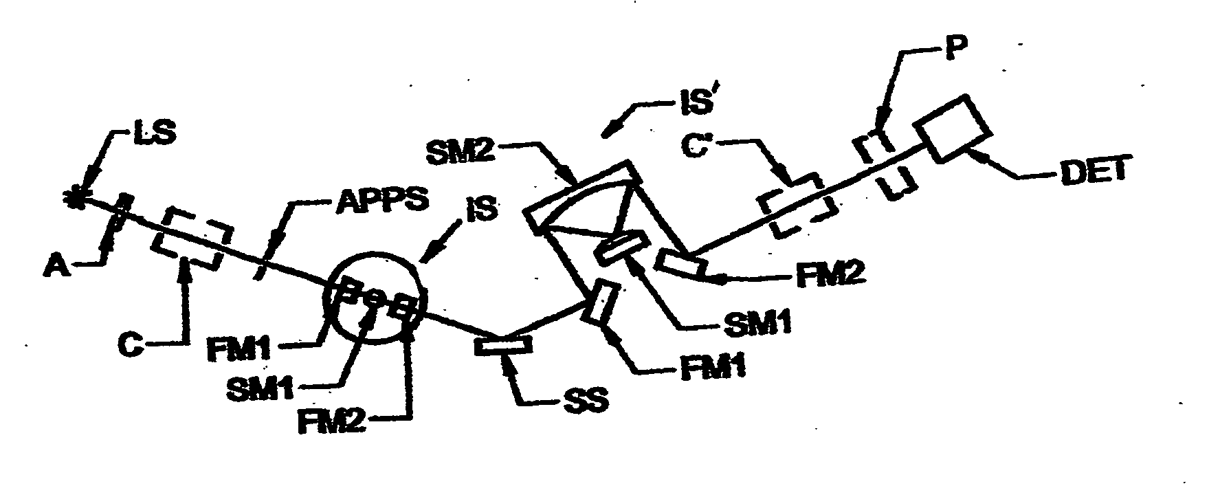
[0276] It is to be appreciated that the distinguishing aspect of the present of the present invention is the presence of at least one combined spatial filter and relay system in the context rotating compensator ellipsometer, polarimeter or the like system as Claimed in Parent patent to Johs, U.S. Pat. No. 5,872,630. Hence, the presentation in the Section of the Specification begins with a detailed disclosure of a background “Offner” relay system, and modified versions thereof as applied in the present invention.

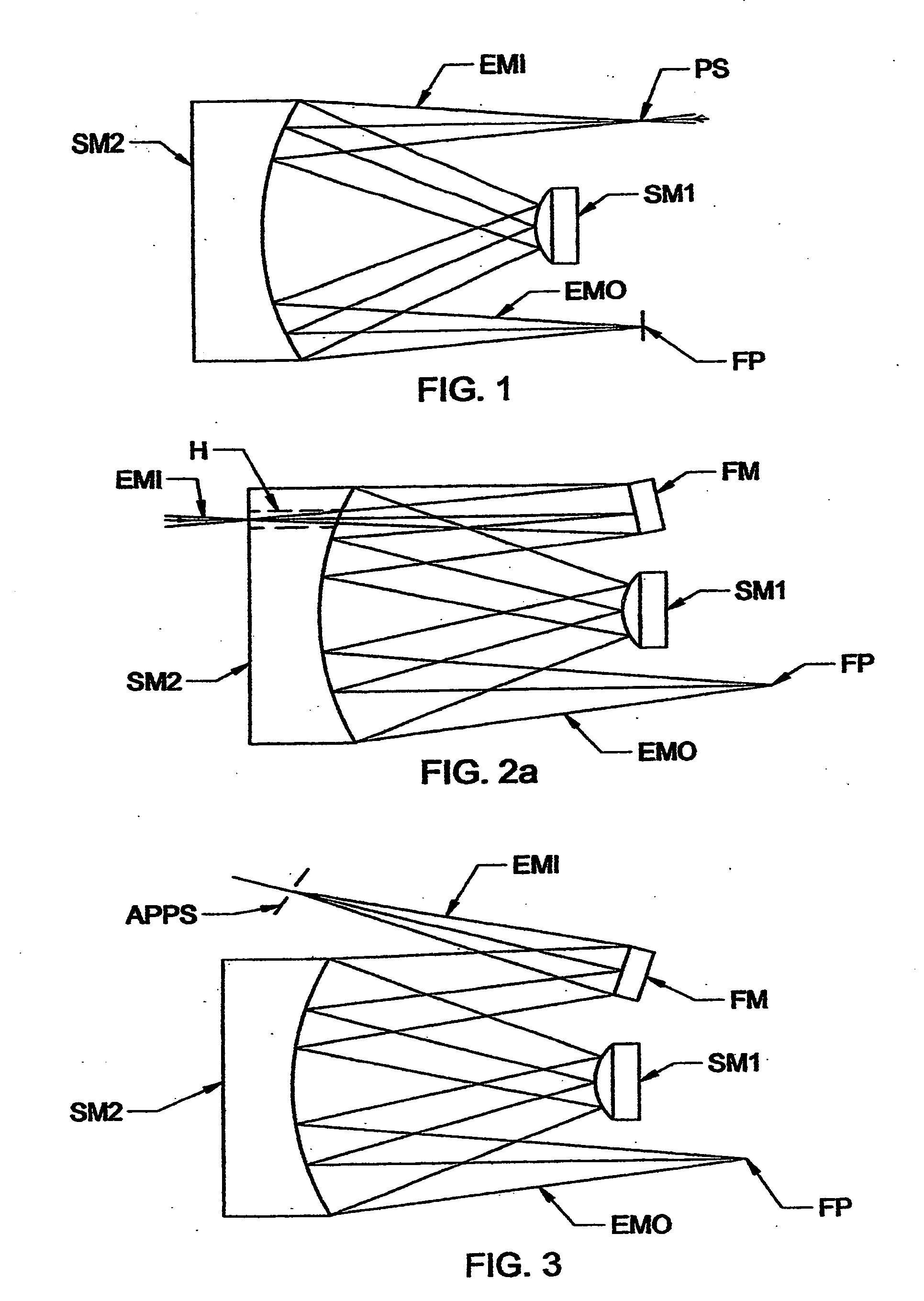
[0277] Turning now to FIG. 1, there is shown a system disclosed in expired U.S. Pat. No. 3,748,015 to Offner. Indicated is a relay system comprising two elements: [0278] a) a concave spherical mirror (SM2); and [0279] c) a convex spherical mirror (SM1).

Said elements (SM2) and (SM1) are arrange such that electromagnetic radiation (EM1) caused to approach the concave spherical mirror (SM2) reflects at a first location thereon, and is reflected to said a convex spherical mirr...


PUM


Abstract

Low aberration relay systems modified to perform as spatial filters in rotating compensator ellipsometer, polarimeter and the like systems.

Description

[0001] This application is a CIP of application Ser. No. 11 / 085,450 Filed Mar. 22, 2005, and threvia of Ser. No. 10 / 928,429, Filed Aug. 27, 2004 and therevia Claims Benefit of Provisional Application 60 / 498,479 Filed Aug. 28, 2003. Further, Benefit of Provisional Application Ser. No. 60 / 576,466 Filed Jun. 3, 2004 is Claimed directly. This application is also a CIP of Co-Pending application Ser. No. 11 / 103,229 Filed Apr. 12, 2005, and of Co-Pending application Ser. No. 10 / 699,540 Filed Nov. 1, 2003, and thervia of application Ser. No. 10 / 034,800 FILED Dec. 28, 2001; and therevia of: Ser. No. 09 / 945,962 filed Sep. 4, 2001 and Ser. No. 09 / 496,011 filed Feb. 1, 2000, (now U.S. Pat. No. 6,353,477); which is a CIP of Ser. No. 09 / 246,888 filed Feb. 8, 1999 (U.S. Pat. No. 6,084,675), which is a CIP of Ser. No. 08 / 912,211 filed Aug. 15, 1997 (U.S. Pat. No. 5,872,630), which is a CIP of Ser. No. 08 / 530,892 filed Sep. 20, 1995 (U.S. Pat. No. 5,666,201); and is a CIP of Ser. No. 08 / 618,820 file...

Claims


Application Information

Patent Timeline
IPC IPC(8): G01J4/00
CPCG01J3/02G01J3/0208G01J3/021G01J3/0229G02B17/008G01J4/00G01N21/21G01N21/211G01N2021/213G01J3/0243
Inventor LIPHARDT, MARTIN M.JOHS, BLAINE D.HALE, JEFFREY S.HERZINGER, CRAIG M.GREEN, STEVEN E.HE, PINGWOOLLAM, JOHN A.
Owner J A WOOLLAM CO
Why Eureka
Try Eureka