Laser light source and laser projection device

A technology of laser light sources and lasers, which is applied in the field of laser projection, can solve the problems of large size, large optical structure, and large volume of laser projection equipment, etc.

Inactive Publication Date: 2016-11-16
HISENSE
View PDF6 Cites 14 Cited by
  • Summary
  • Abstract
  • Description
  • Claims
  • Application Information

AI Technical Summary

Problems solved by technology

When the beam spot is large, the diameters of the convex lens 1 and the concave lens 2 in the telescope system are required to increase accordingly, resulting in a large volume of the optical structure, and sufficient optical space needs to be reserved between the convex lens and the concave lens in the telescope system.

Method used


Image

  • Laser light source and laser projection device
  • Laser light source and laser projection device
  • Laser light source and laser projection device

Examples


Embodiment Construction

[0021] Typical embodiments that embody the features and advantages of the present invention will be described in detail in the following description. It should be understood that the present invention is capable of various changes in different embodiments without departing from the scope of the present invention, and that the description and illustrations therein are illustrative in nature and not limiting. this invention.

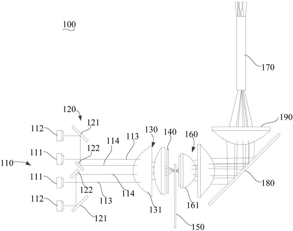
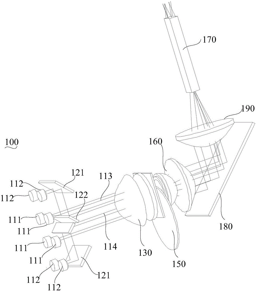
[0022] The present invention provides a laser projection device 10 . The laser projection device includes a laser light source 100 . see figure 2 and image 3 , the laser light source 100 includes a laser array 110 and a plurality of narrowing reflectors 120 .

[0023] The laser array 110 includes a main laser 111 and secondary lasers 112 located on two sides of the main laser 111 . The main laser 111 is located in the middle of the laser array 110 . The secondary laser 112 is located around the primary laser 111 . The primary laser 111 emits a pri...


PUM


Abstract

The invention provides a laser projection device and a laser light source thereof. The laser light source comprises a laser array and a plurality of beam-contraction reflectors. The laser array consists of a main laser and secondary lasers arranged at the two sides of the main laser; the main laser is arranged at the middle part of the laser array and emits a main light beam; and the secondary lasers emit secondary light beams. The beam-contraction reflectors include first reflection planes and second reflection planes. According to the laser light source, the secondary light beams emitted by the secondary lasers are reflected by the first reflection planes and the second reflection planes and thus the secondary light beams located at the two sides of the main light beam approach the main light beam, thereby achieving an objective of beam contraction. Therefore, a telescopic system with a small diameter dimension can meet the using requirement; the size of the overall laser light source is reduced; and microminiaturization development of the laser projection device can be realized well.

Description

technical field [0001] The invention relates to the field of laser projection, in particular to a laser light source and laser projection equipment. Background technique [0002] For the laser light source technology of laser projection equipment, the laser is usually irradiated on the phosphor wheel coated with phosphor powder to form three primary colors. Since the spot area of ​​the laser beam is larger after exiting from the laser array, and the spot size required for excitation on the fluorescent wheel is smaller, it is necessary to perform beam shaping to meet the spot size required for fluorescence excitation. In a beam shaping optical path in the prior art, such as figure 1 As shown, a telescope system consisting of a convex lens 1 and a concave lens 2 is used to shrink the beam of the laser light first. [0003] as well as, figure 1 shows a reflective fluorescent wheel 4 structure, including a laser transmission area and a fluorescent area, when the blue laser li...

Claims


Application Information

Patent Timeline
IPC IPC(8): G03B21/20G02B27/48
CPCG03B21/2033G02B27/48G03B21/204G03B21/2066G03B21/208
Inventor 王强
Owner HISENSE
Why Eureka
Try Eureka