Remote enclosure systems and methods of production thereof

a technology of remote enclosure and enclosure system, which is applied in the field of remote enclosure system, can solve the problems of difficult, if not impossible, access to other components, difficult repair, replacement or access to difficult to access components, and reduce the problems inherent in conventional electronic setup, and achieves easy configuration and expansion.

Inactive Publication Date: 2006-11-30
PURCELL SYST
View PDF9 Cites 18 Cited by
  • Summary
  • Abstract
  • Description
  • Claims
  • Application Information

AI Technical Summary

Benefits of technology

[0009] Remote enclosure systems have now been designed and are described herein that meet the following goals: a) consolidate electrical terminations in one system; b) pre-terminate AC and DC equipment loads before site installation; c) provide multiple access points for facilitating equipment repair and installation; d) are easily configurable and expanded through the use of a modular frame design that accommodates a variety of customized side panels or the attachment of a variety of expansion cabinets; e) are aesthetically functional given the cable entry and routing structure; f) provide exceptional thermal management and g) reduce problems inherent in conventional electronic setups.

Problems solved by technology

Remote sites usually contain electrical and telecommunications wiring and components, such as batteries, antennae, circuit boards, keypads and other related components that in many cases can be fragile, relatively inaccessible and certainly sensitive to the elements and other environmental conditions.
Conventional enclosure systems are configured as a cabinet arrangement and are either built to standard specifications then modified on-site or are built to custom specifications—which presents manufacturing / assembly line issues and problems.
Often times, in conventional remote enclosure systems, some components will be easy to access, swap out and repair; but other components will be difficult, if not impossible, to access without moving other components around or removing them altogether.
The process of repairing, replacing or accessing difficult to access components can be made more difficult depending on the site location of the remote enclosure system and the environmental conditions surrounding the remote enclosure system.
Remote enclosure systems also present other layers of complexity when reviewing the viability of a remote site.

Method used


Image

  • Remote enclosure systems and methods of production thereof
  • Remote enclosure systems and methods of production thereof
  • Remote enclosure systems and methods of production thereof

Examples


Embodiment Construction

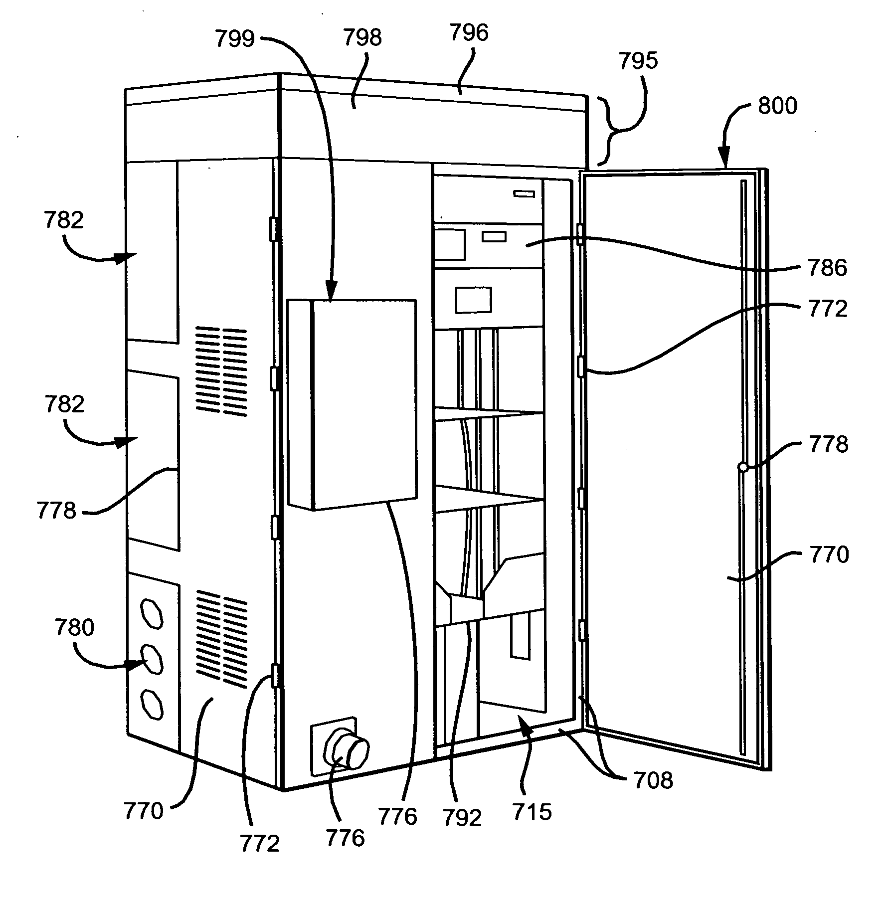
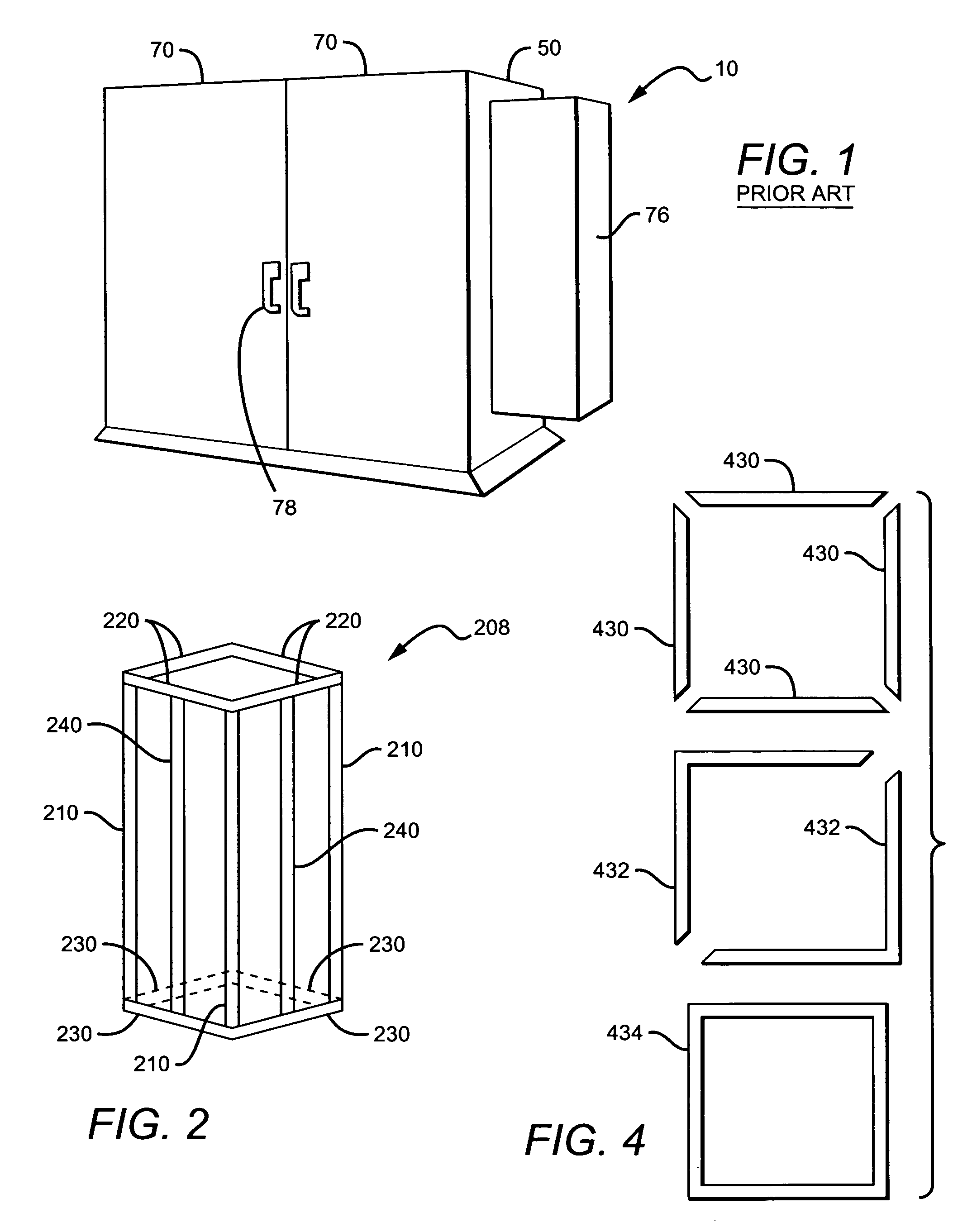
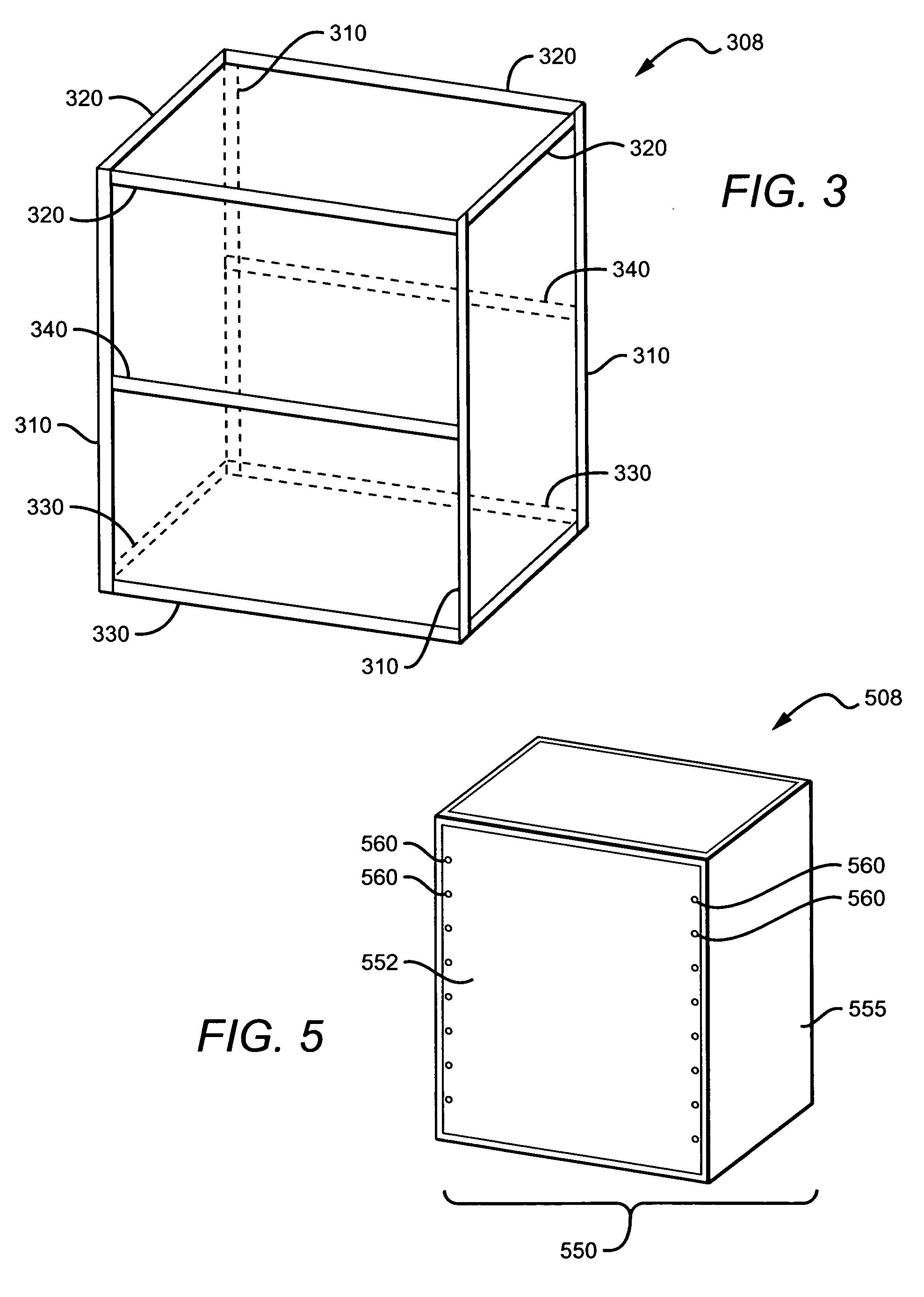
[0020] Remote enclosure systems have now been designed and are described herein that meet the following goals: a) consolidate electrical terminations in one system; b) pre-terminate AC and DC equipment loads before site installation; c) provide multiple access points for facilitating equipment repair and installation; d) are easily configurable and expanded through the use of a modular frame design that accommodates a variety of customized side panels or the attachment of a variety of expansion cabinets; e) are aesthetically functional given the cable entry and routing structure; f) provide exceptional thermal management and g) reduce problems inherent in conventional electronic setups.

[0021] Remote enclosure systems contemplated generally comprise: a) a frame system further comprising at least two side panels; b) at least one door coupled to the frame system; c) a cable management assembly coupled to the frame system; d) at least one removable radiofrequency (RF) management system...


PUM


Abstract

Remote enclosure systems have now been designed and are described herein that meet the following goals: a) consolidate electrical terminations in one system; b) pre-terminate AC and DC equipment loads before site installation; c) provide multiple access points for facilitating equipment repair and installation; d) are easily configurable and expanded through the use of a modular frame design that accommodates a variety of customized side panels or the attachment of a variety of expansion cabinets; e) are aesthetically functional given the cable entry and routing structure; f) provide exceptional thermal management and g) reduce problems inherent in conventional electronic setups. Remote enclosure systems contemplated generally include: a) a frame system further comprising at least two side panels; b) at least one door coupled to the frame system; c) a cable management top assembly coupled to the frame system; d) at least one removable radiofrequency (RF) management system, such as at least one RF port plate, at least one RF port, at least one RF cable or any other suitable system for managing RF signals and a combination thereof, coupled to at least one of the side panels, coupled to and / or located within the cable management top assembly and / or coupled to and / or located within the frame system or a combination thereof and e) a bottom panel coupled to the frame system. The remote enclosure system may also comprise any number of components suitable for electronics, wireless and cable-based data and telecommunications applications, including air conditioner exhaust member, an air conditioner unit, a battery pack, a meter base, a power receptacle box, an alarm system or alarm device, an expansion cabinet, a coupling device or system, a pre-wiring system and / or a demarcation component.

Description

[0001] This application claims priority to U.S. Provisional Application No. 60 / 379,480 filed on May 10, 2002, PCT Application Ser. No.: PCT / US02 / 34800 filed on Oct. 30, 2002 and is a continuation in part of U.S. Utility Application Ser. No. 10 / 481306 filed on Dec. 17, 2003, which are commonly-owned and incorporated herein in their entireties by reference.BACKGROUND [0002] The telecommunications and data communications industries have grown exponentially in the last 5 to 8 years partly because both industries have been able to expand their customer base from customers that are close to the center of operations / transmissions to customers who are located a significant distance from the center of operations / transmissions. Expansion of data transmissions to customers located at significant distances from the center of operations is facilitated by remote sites that are portable and smaller than the center of operations site. Both industries include those utilities and industries that prov...

Claims


Application Information

Patent Timeline
Patent Type & Authority Applications(United States)
IPC IPC(8): H05K7/14H04M19/00H04N7/173H04Q1/02H04Q1/06H05K7/18
CPCH04M19/00H04Q1/06H04Q2201/02H04Q2201/06H04Q2201/10H04Q1/03H05K7/186H04Q1/035H04Q1/11H04Q1/026H05K7/183
Inventor MILLER, WILLIAMJOHNSON, KELLY
Owner PURCELL SYST
Why Eureka
Try Eureka