Methods and devices for driving a piezoelectric pump

Pending Publication Date: 2022-01-13
TTP VENTUS LTD
View PDF0 Cites 0 Cited by
  • Summary
  • Abstract
  • Description
  • Claims
  • Application Information

AI Technical Summary

Benefits of technology

The patent describes a portable disc pump device that has a control system to efficiently control the drive and output parameters, and a reliable fault prevention mechanism to avoid overdriving the actuator. The device uses a DC-to-AC conversion circuit to amplify power from a portable power source and power a microfluidic pump. The device also has a DC gain circuit for reliable amplification of power, a square-like waveform for efficient driving, and a ratio adjustment to create a waveform with attenuated harmonics. Additionally, the device uses PWM to generate complex drive waveforms with increased efficiency. The DC gain unit may contain a coupled inductor for withstanding high voltages required for driving the actuator, and the DC to AC conversion unit may contain operational amplifiers or MOSFETs for efficient power conversion.

Problems solved by technology

However, in practice, due to differences resulting from manufacturing, and variations in operational conditions, the resonant frequency of the piezoelectric actuator within a disc pump varies.
Using a single pre-determined voltage waveform to drive a disc pump can result in the disc pump not reaching its maximum potential output capabilities.

Method used


Image

  • Methods and devices for driving a piezoelectric pump
  • Methods and devices for driving a piezoelectric pump
  • Methods and devices for driving a piezoelectric pump

Examples


Embodiment Construction

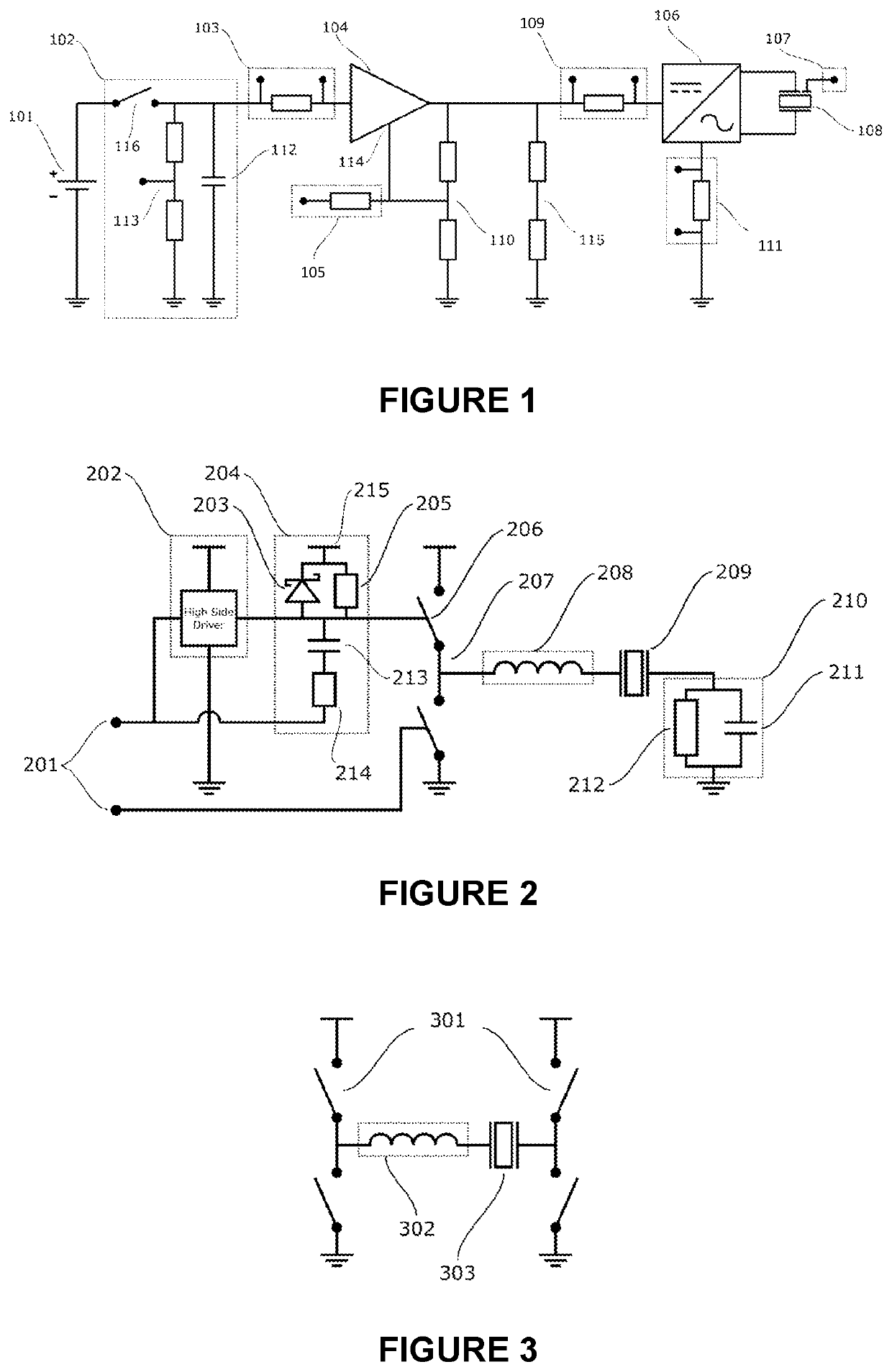
[0033]FIG. 1 schematically illustrates an example circuit 100 used to drive a piezoelectric actuator in a potable pump according to an example of the present invention, with several optional additions for measurement and control purposes.

[0034]The circuit 100 includes a battery 101 grounded at one end and connected at the other end to the input of a DC gain section 104 through an input measurement circuit 102 and a first shunt resistor 103. A first resistor divider 110 is connected between the output of the DC gain section 104 and ground. The centre of the first resistor divider 110 is connected back to a feedback pin 114 of the DC gain section 104. A second shunt resistor 105 is placed between the centre of the first resistor divider 110 and the feedback pin 114. A second resistor divider 115 is connected between the output of the DC gain section 104 and ground, where the centre of the second resistor divider is arranged to be connected to an analogue-to-digital converter (ADC, not...


PUM


Abstract

A voltage driving apparatus for a portable fluid pump comprising a power source arranged to provide a direct current, a DC gain unit electrically connected, in use, to receive a voltage from the power source and output an amplified voltage, and a DC to AC conversion unit arranged, in use, to receive the amplified voltage from the DC gain unit and output a periodic waveform to drive a piezoelectric actuator in the portable fluid pump. The output periodic waveform comprises a first discrete voltage level and a second discrete voltage level. Each period of the waveform comprises the first voltage level for a first length of time and a second voltage level for a second length of time.

Description

[0001]The present invention relates to methods and devices for driving a piezoelectric disc pump.[0002]Recent developments in non-linear acoustics and valve design have allowed the development of compact pumps containing a disc shaped cavity, with the capability of high pressure output and silent operation.[0003]Such a ‘disc pump’ is well suited to portable applications due to its small size, efficiency and silent operation. The actuator within such a disc pump requires an alternating current (AC) at a drive voltage of several tens of volts peak to peak at maximum power. In order to allow the disc pump to be efficiently utilised in a portable application, it is necessary to provide a compact way of portably providing high voltage AC power to the pump. Batteries are normally used to power portable devices, typically outputting a direct current (DC) at around 3.7 volts (V), so there is a need for drive circuitry for such disc pumps that can employ DC battery sources yet still drive th...

Claims


Application Information

Patent Timeline
IPC IPC(8): F04B43/04F04B49/06
CPCF04B43/046H02M7/537F04B49/06H02M3/335F04B2203/0402F04B17/003
Inventor DEEKS, WILLIAMHARRISON, TOM
Owner TTP VENTUS LTD
Why Eureka
Try Eureka