A multilayer ridged waveguide antenna feed structure

An antenna feeding and waveguide structure technology, which is applied to linear waveguide feeding arrays, antennas, antenna arrays, etc., can solve the problems of difficult processing and assembly, complicated boundary shapes of ridge waveguides, etc., and achieves high power capacity and easy expansion of the antenna aperture. , the effect of simple structure

Active Publication Date: 2022-07-05
ZHEJIANG UNIV +1
View PDF18 Cites 0 Cited by
  • Summary
  • Abstract
  • Description
  • Claims
  • Application Information

AI Technical Summary

Problems solved by technology

However, due to the complex boundary shape of the ridge waveguide, it is generally difficult to process and assemble in large arrays.

Method used


Image

  • A multilayer ridged waveguide antenna feed structure
  • A multilayer ridged waveguide antenna feed structure
  • A multilayer ridged waveguide antenna feed structure

Examples


Embodiment Construction

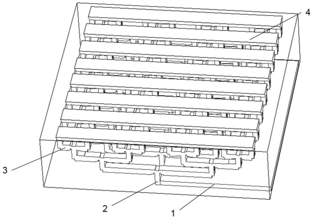
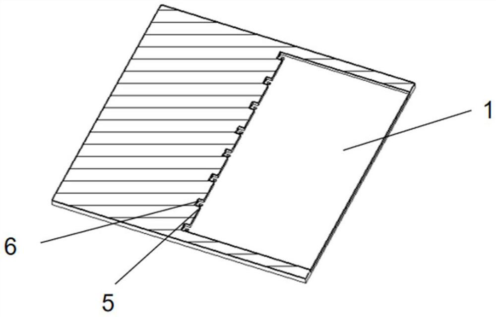
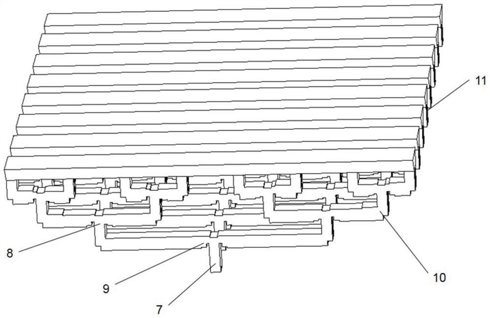
[0052] Since the present invention works in the microwave and millimeter wave frequency band, the influence of the loss of the transmission line needs to be considered in the design process, so the waveguide structure is used as the main structure of the transmission line for design. In a certain frequency band, when the frequency remains unchanged, different waveguide heights will lead to different propagation constants and different waveguide characteristic impedances. Therefore, we can design an equal power divider with lower loss and a different waveguide height by changing the waveguide height. Equal power divider, which forms the H-plane power distribution structure of the ridged waveguide that we show. At the same time, since the antenna gain increases with the increase of the antenna output aperture, multiple ridge waveguide H-plane power distribution structures can be stacked one after the other, each layer can correspond to the radiation structure of a line array, and...


PUM


Abstract

The invention discloses a multi-layer ridge waveguide antenna feeding structure, which comprises: a ridge waveguide-parallel waveguide broadside discretization structure and a ridge waveguide H-plane power distribution structure; the ridge waveguide-parallel plate waveguide broadside discretization structure; The parallel-plate waveguide structure is used for the discretization of planar electromagnetic waves in the direction of the parallel-plate waveguide, including the parallel-plate waveguide structure, the metal baffle, the mode conversion structure, and the output port of the multi-channel ridge waveguide-parallel-plate waveguide broadside discretization structure; the parallel-plate waveguide structure The end of the structure is provided with a number of metal partitions arranged at equal intervals, and a mode conversion structure is arranged in the center between adjacent metal partitions to connect the output ports of each ridge waveguide-parallel waveguide broadside discretization structure; the ridges The input port of the waveguide H-plane power distribution structure is connected to the output port of each ridge waveguide-parallel-plate waveguide broadside discretization structure, which is used for uniform or non-uniform distribution of energy in the propagation direction of the parallel-plate waveguide.

Description

technical field [0001] The present invention relates to the technical field of antennas and antenna feeds, and in particular to flat panel antennas for mobile and aviation applications. Background technique [0002] With the development of wireless communication technology, the demand for wireless broadband channels for high-speed data transmission is increasing. Especially in the field of mobile satellite communication, there is a lack of antennas that can meet the requirements of mobile use, specifically, high gain, small size, and light weight. 's antenna. The continuous growth of high-throughput communication demand makes millimeter waves widely used in modern wireless communication systems. The frequency range of millimeter waves is between 30 and 300 GHz, with a total bandwidth of about 250 GHz. The frequency band is between microwave and infrared light waves, which is different from traditional Compared with microwave systems, millimeter wave not only has the advanta...

Claims


Application Information

Patent Timeline
Patent Type & Authority Patents(China)
IPC IPC(8): H01Q21/06H01Q21/00
CPCH01Q21/064H01Q21/0037
Inventor 吴锡东冀俊超杨喆栋周金芳
Owner ZHEJIANG UNIV
Why Eureka
Try Eureka