Backlight device and liquid crystal display device

a liquid crystal display and backlight technology, applied in the field of backlight devices, can solve the problem of greatly reduced luminan

Inactive Publication Date: 2006-11-30
SHARP KK
View PDF12 Cites 1 Cited by
  • Summary
  • Abstract
  • Description
  • Claims
  • Application Information

AI Technical Summary

Benefits of technology

[0022] According to the above-mentioned present invention, the protruding part formed on the reflector serves as a stopper so that the side surface of the light-guiding plate contacts with the protruding part and cannot enter further inside the reflector when the light-guiding plate moves toward the reflector. Therefore, the light-guiding plate never contact with the light source retained inside the reflector, thereby preventing the light source from being damaged.
[0023] Moreover, a contact area between the reflector and the retaining member is increased by forming the protruding part at a position where the light source is brought into contact with the retaining member of the light source, and, thus, heat is released through the reflector and a cooling effect to cool the light source can be raised.

Problems solved by technology

However, if such a structure is made, an area of the opening part, through which the light introduced from the reflector into the light-guiding plate passes, is reduced, which may generate a problem that a luminance is greatly reduced.

Method used


Image

  • Backlight device and liquid crystal display device
  • Backlight device and liquid crystal display device
  • Backlight device and liquid crystal display device

Examples


Embodiment Construction

[0033] Next, a description will be given, with reference to the drawings, of embodiments of the present invention.

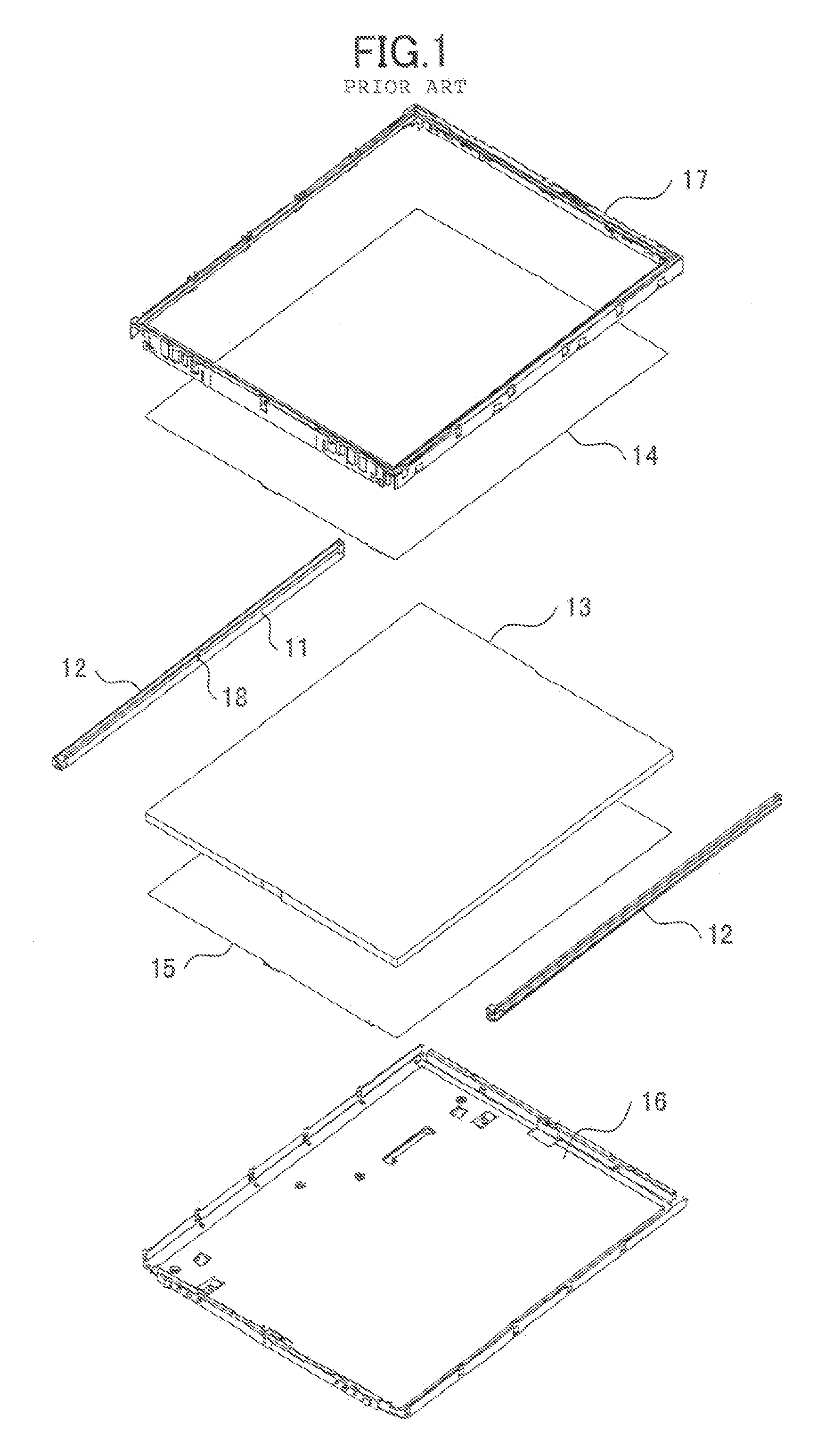
[0034]FIG. 4 is a plan view of a backlight device according to a first embodiment of the present invention. FIG. 5 is an enlarged cross-sectional view taken along a line V-V in FIG. 4. Since the backlight device according to the first embodiment of the present invention has the same fundamental structure as the backlight device shown in FIG. 1, parts that are the same as the parts shown in FIG. 1 are given the same reference numerals, and descriptions thereof will be omitted.

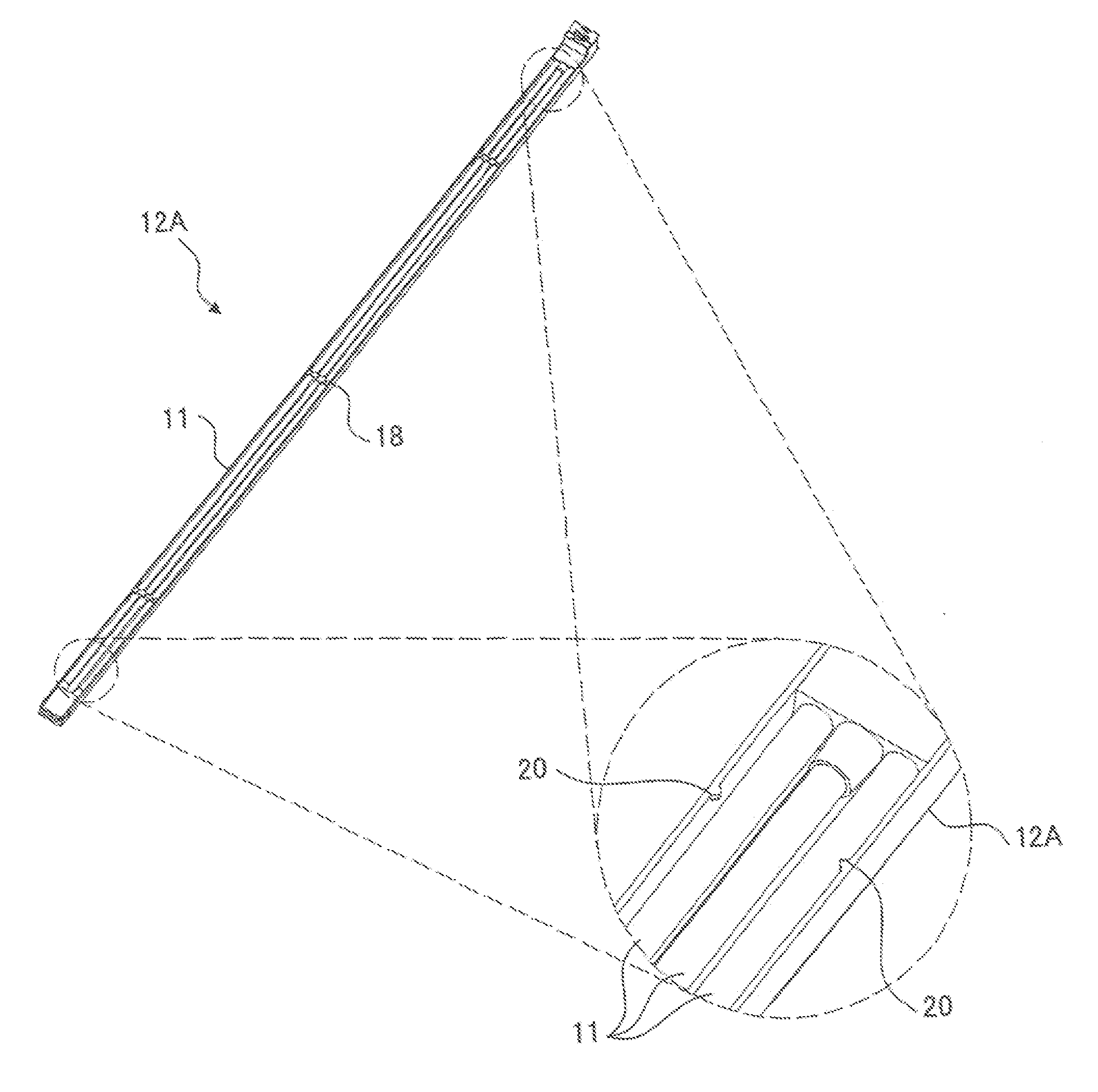
[0035] The backlight device according to the first embodiment of the present invention shown in FIG. 4 differs from the backlight device shown in FIG. 1 in that a reflector 12A is processed. Light is uniformly emitted from the surface of the diffusion plate 14 shown in FIG. 4 so as to illuminate a liquid crystal panel (not shown in the figure) arranged on the frame 17.

[0036] In the present embodim...


PUM


Abstract

A backlight device is incorporated into a liquid crystal display device so as to illuminate a liquid crystal panel from a backside. The backlight device includes a light-guiding plate emitting a light, which is incident on a side surface thereof, from a front surface, and a reflector arranged along the side surface of the light-guiding plate so as to reflect a light from a light source accommodated inside thereof and guide the light to the side surface of the light-guiding plate through an opening part. A least one minute protruding part, which protrudes in a direction parallel to the side surface of said light-guiding plate, is formed on an edge part of the opening part of the reflector facing the light-guiding plate. The side surface of the light-guiding plate is brought into contact with the protruding part of the reflector when the light-guiding plate moves toward the reflector.

Description

BACKGROUND OF THE INVENTION [0001] 1. Field of the Invention [0002] The present invention relates to backlight devices for backside illumination of liquid crystal display device and, more specifically, to an edge-light type backlight device which introduces a light from a side surface of a light-guiding plate made of a transparent plate. [0003] 2. Description of the Related Art [0004] A liquid crystal panel of a liquid crystal display device performs a screen display by not emitting a light by itself but transmitting and interrupting a light by a polarization action. Therefore, generally, a backlight device, which illuminates a liquid crystal panel from a backside, is incorporated in a liquid crystal display device. [0005]FIG. 1 is an exploded perspective view of a conventional backlight device. The conventional backlight device shown in FIG. 1 comprises reflectors 12, in which fluorescent tubes 11 or the like as a light source are accommodated and held, and a light-guiding plate 13...

Claims


Application Information

Patent Timeline
Patent Type & Authority Applications(United States)
IPC IPC(8): F21V7/04
CPCG02B6/0031G02B6/0068G02B6/0091G02B6/009G02B6/0071G02F1/1335
Inventor BESSHO, HISANORI
Owner SHARP KK
Why Eureka
Try Eureka