
Perpendicular magnetic recording medium and perpendicular magnetic recording/reproducing apparatus

a technology of perpendicular magnetic recording and recording medium, which is applied in the direction of magnetic recording, data recording, instruments, etc., can solve the problems of easy deterioration of crystal orientation, difficult further reduction, and often natural determination of grain siz

Active Publication Date: 2006-11-30
KK TOSHIBA
View PDF3 Cites 17 Cited by
  • Summary
  • Abstract
  • Description
  • Claims
  • Application Information

AI Technical Summary

Benefits of technology

[0007] Also, the magnetic recording layer is becoming thinner and thinner, and the signal output lower and lower. Therefore, if the crystal grain density greatly decreases, it is necessary to greatly increase the saturation magnetization of the magnetic crystal grains in order to maintain the output. To increase the saturation magnetization, a large change in composition is generally required. However, the segregated structure and crystal orientation are often disrupted, increases the medium noise, so this method is also not easy to put into practice.
[0009] A general architecture that implements the various feature of the invention will now be described with reference to the drawings. The drawings and the associated descriptions are provided to illustrate embodiments of the invention and not to limit the scope of the invention.

Problems solved by technology

However, in the method of simply stacking thin films, the grain size is often naturally determined and cannot be unconditionally controlled.
Also, when a granular recording layer is used as the magnetic recording layer, the average grain diameter can be reduced to about 6 nm, but further reduction has been found to be very difficult.
Although it is being attempted to further reduce the crystal grain size of the magnetic crystal grains by using a granular structure in which the grains are segregated in an amorphous matrix, the crystal grains did not easily grow into columns, the crystal orientation readily deteriorated, and the crystal grain density was low by using this method.
In the granular structure described above, however, the crystal orientation generally worsens and often becomes random, and this greatly increases the medium noise.
However, the segregated structure and crystal orientation are often disrupted, increases the medium noise, so this method is also not easy to put into practice.
In practice, however, it is physically very difficult to realize a state in which fine nuclei spread such that they do not form a continuous film but separate from each other, in case of depositing, on the nuclei, magnetic crystal grains in an amount with which a continuous film can be formed.

Method used


Image

  • Perpendicular magnetic recording medium and perpendicular magnetic recording/reproducing apparatus
  • Perpendicular magnetic recording medium and perpendicular magnetic recording/reproducing apparatus
  • Perpendicular magnetic recording medium and perpendicular magnetic recording/reproducing apparatus

Examples


experimental embodiment 1

[0112] Manufacture of perpendicular magnetic recording medium

[0113] A disk-like cleaned glass substrate (manufactured by Ohara, outer diameter=2.5 in.) was prepared as a nonmagnetic substrate. This glass substrate was placed in a film formation chamber of a magnetron sputtering apparatus (C-3010 manufactured by Anelva), and the film formation chamber was evacuated until the base pressure of 2×10⁻⁵ Pa or less. After that, sputtering was sequentially performed as follows in an Ar ambient at a gas pressure of 0.6 Pa.

[0114] First, a 100-nm thick CoZrNb alloy was formed as a soft magnetic layer on the nonmagnetic substrate.

[0115] Then, a multilayered underlayer including first, second, and third metal underlayers was formed as follows.

[0116] Next, a 5-nm thick Ti film was formed as the first metal underlayer.

[0117] Measurements were performed using an atomic force microscope (AFM) and X-ray diffractometer (XRD) in a case in which a Ti layer was stacked on a CrZrNb soft magnetic laye...

experimental embodiment 2

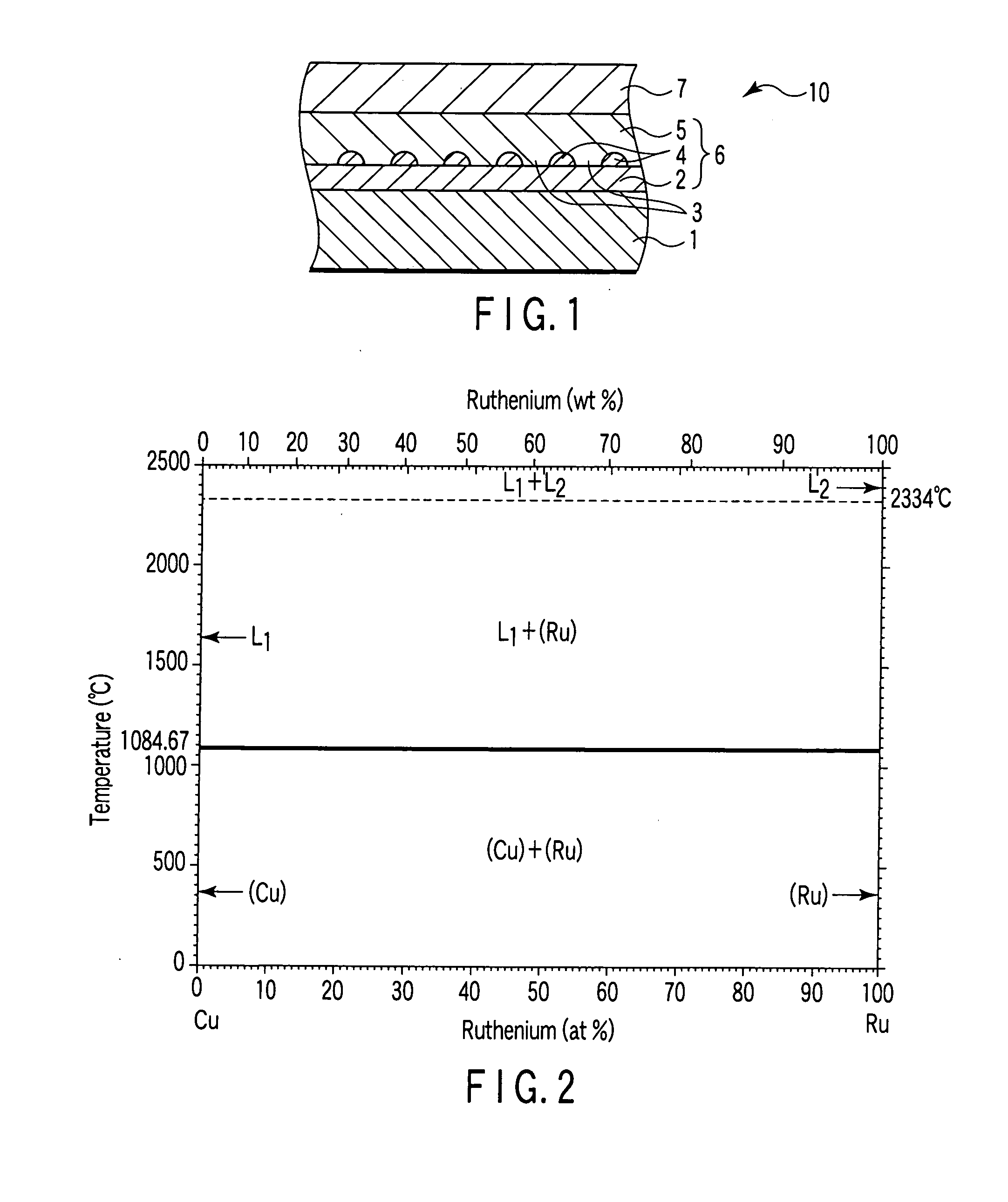
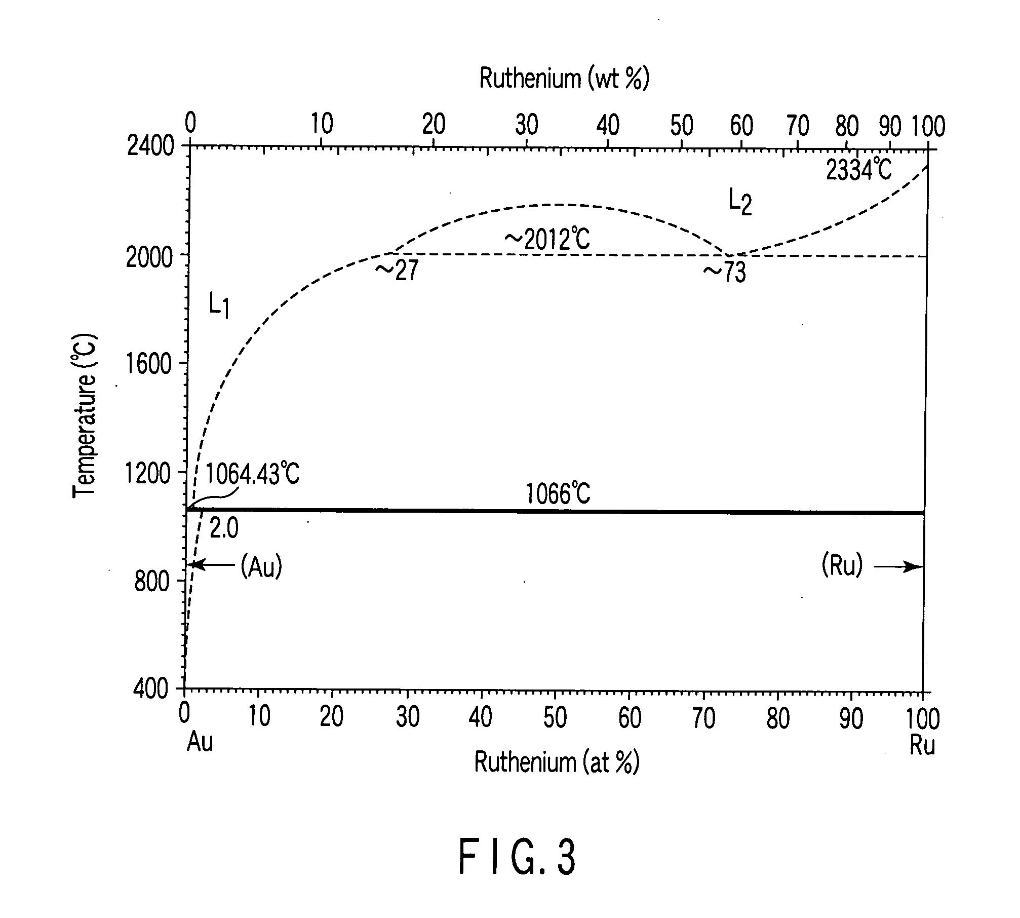
[0166] Perpendicular magnetic recording media were manufactured following the same procedures as in Experimental Embodiment 1 except that Ni, Rh, Pd, Pt, Ag, and Au having the same fcc as Cu were used as the second metal underlayer instead of Cu.

[0167] As in Experimental Embodiment 1, to check the growth of metal crystal grains, the film formation was stopped when these second metal materials were sputtered, and AFM measurements were performed.

[0168] The surface roughness increased when the sputtering amount of the second metal underlayer was increased or decreased, where necessary, within the range equivalent to an average layer thickness of about 0.5 to 2 nm. Therefore, it is presumably possible, depending on the film formation conditions, to form metal grains into islands and obtain a second metal underlayer having holes, regardless of the metal material used as the second metal underlayer.

[0169] Then, to check the grain size of Ru, plane view TEM observation was performed on ...

experimental embodiment 3

[0174] Perpendicular magnetic recording media were manufactured following the same procedures as in Experimental Embodiment 1 except that Ni, Rh, Pd, Pt, Ag, Au, Nb, and Ta were used as the first metal underlayer instead of Ti.

[0175] As in Experimental Embodiment 1, to check the growth of metal grains, the film formation was stopped when Cu was sputtered on the first metal underlayer, and AFM measurements were performed.

[0176] The surface roughness increased when the sputtering amount of Cu was increased or decreased, where necessary, within the range equivalent to an average layer thickness of about 0.5 to 2 nm.

[0177] Since the sputtering amount was small, therefore, it is presumably possible, depending on the film formation conditions, to form metal grains into islands and obtain a second metal underlayer having holes on the first metal underlayer, regardless of the metal material.

[0178] Then, to check the grain size of Ru, plane view TEM observation was performed on the state...


PUM


Abstract

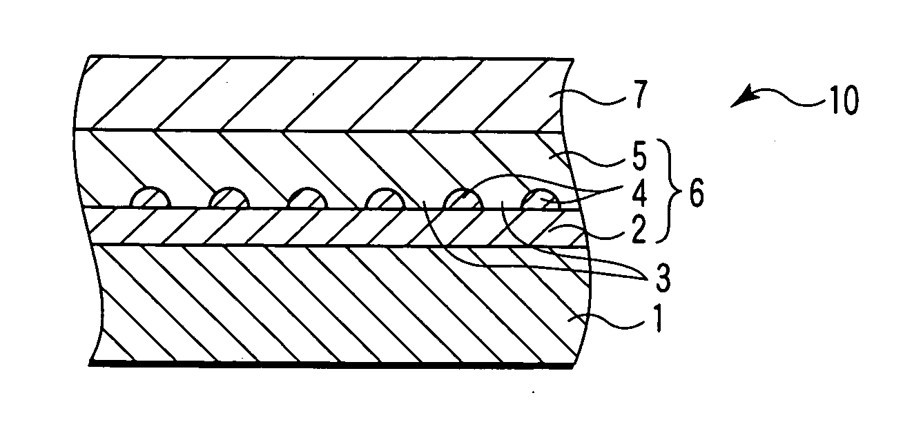
In a perpendicular magnetic recording medium, a multilayered underlayer including a first metal underlayer, a second metal underlayer having no solid solution properties with respect to the first metal underlayer and having a hole, and a third metal underlayer having solid solution properties with respect to the first metal underlayer and having no solid solution properties with respect to the second metal underlayer is formed on a substrate, and a magnetic recording layer is formed on the multilayered underlayer.

Description

CROSS-REFERENCE TO RELATED APPLICATIONS [0001] This application is based upon and claims the benefit priority of from Japanese Patent Application No. 2005-155996, filed May 27, 2005, the entire contents of which are incorporated herein by reference. BACKGROUND [0002] 1. Field [0003] The present invention relates to a perpendicular magnetic recording medium for use in, e.g., a hard disk drive using the magnetic recording technique, and a perpendicular magnetic recording / reproducing apparatus. [0004] 2. Description of the Related Art [0005] Recent hard disk drives have become smaller and smaller, and a product having a disk diameter of 1 inch. or less has been proposed. In addition, to realize an inexpensive, high-speed, large-capacity recording medium, the recording density is required to further increase. One of the most effective methods of increasing the areal recording density of a magnetic recording medium is to reduce noise by reducing the size of the magnetic crystal grains in...

Claims


Application Information

Patent Timeline
IPC IPC(8): G11B5/66
CPCG11B5/8404G11B5/7325G11B5/7369G11B5/737
Inventor OIKAWA, SOICHI
Owner KK TOSHIBA
Learn More