Cooling system for continuous variable transmission of vehicle

a technology of transmission and cooling system, which is applied in the direction of guards, couplings, cycle equipment, etc., can solve the problems of increasing heat, affecting the reliability of the v-belt used in the cvt, and insufficient so as to achieve the effect of effective cooling of the cvt and a larger passenger compartmen

Inactive Publication Date: 2006-11-30
YAMAHA MOTOR CO LTD +1
View PDF5 Cites 105 Cited by
  • Summary
  • Abstract
  • Description
  • Claims
  • Application Information

AI Technical Summary

Benefits of technology

[0011] To overcome the problems described above, preferred embodiments of the present invention provide a cooling system for a CVT of an of

Problems solved by technology

However, conventional cooling systems have been unable to provide sufficient cooling of the CVT, especially in SSVs, which produce a much larger load than that produced by conventional ATVs.
The increased heat deteriorates the reliability of the V-belt used in the CVT.
Thus, conventional cooling systems are not suitable for us

Method used


Image

  • Cooling system for continuous variable transmission of vehicle
  • Cooling system for continuous variable transmission of vehicle
  • Cooling system for continuous variable transmission of vehicle

Examples


Embodiment Construction

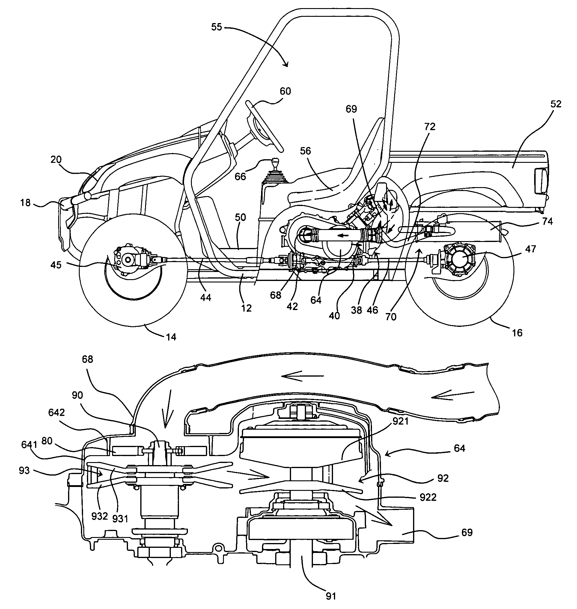
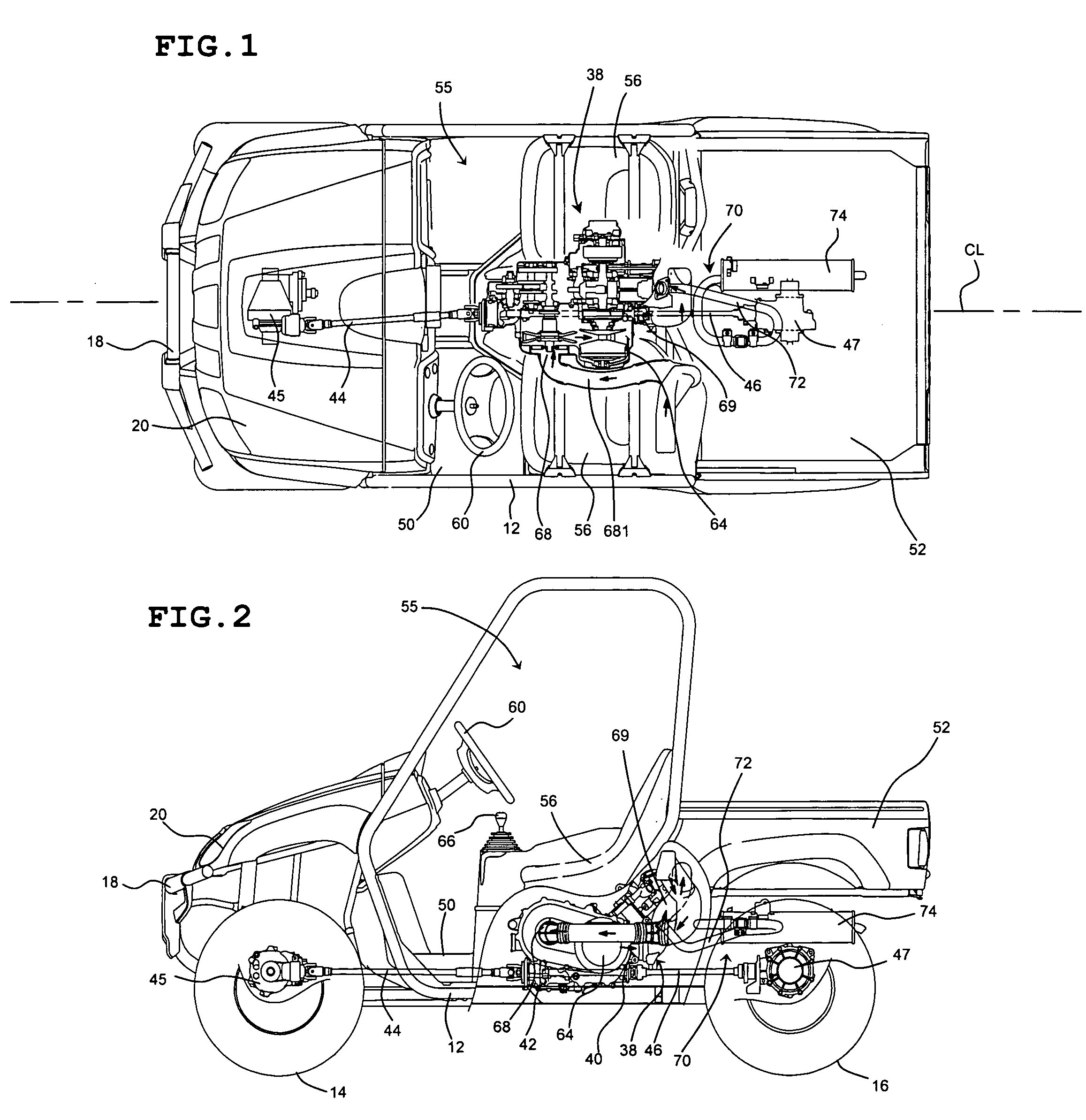
[0030] With reference to FIGS. 1 and 2, an off-road vehicle, which is generally indicated by the reference numeral 10, will be described, however, the present invention is not limited thereto and relates to any type of vehicle in which a CVT is used. The vehicle 10 is preferably arranged and configured in accordance with preferred embodiments of the present invention. More particularly, the vehicle 10 preferably includes an exhaust system, which will be described below, that is arranged and configured in accordance with preferred embodiments of the present invention.

[0031] While the present invention will be described in the context of the illustrated vehicle 10, which is preferably an SSV, it should be understood that the present invention may also be applied to various types of vehicles. For instance, although the illustrated vehicle 10 includes four wheels, the present invention could be used on motor vehicles having two wheels, three wheels or more than four wheels. In addition...


PUM


Abstract

A vehicle includes a frame assembly, an engine mounted on the frame assembly, and a continuous variable transmission connected to the engine. The continuous variable transmission includes a housing including an air intake duct and an exhaust duct, a drive shaft disposed in the housing, a drive pulley including at least one sheave disposed on the drive shaft, a driven shaft disposed in the housing and spaced from the drive shaft, a driven pulley including at least one sheave disposed on the driven shaft, and a fan disposed on the driven shaft. The fan is disposed between an inner surface of the housing and the driven pulley so as to be spaced from the driven pulley. The air intake duct defines an opening in the housing for providing air from outside the housing into the housing, and the air intake duct is axially aligned with the driven shaft and the fan disposed thereon, such that the air flows directly into the fan and is directed to the driven pulley.

Description

BACKGROUND OF THE INVENTION [0001] 1. Field of the Invention [0002] The present invention relates to a continuously variable transmission (CVT) cooling system for a vehicle, such as an All-Terrain Vehicle (ATV), Side-by-Side Vehicle (SSV) or other off-road vehicle. More particularly, the present invention relates to a CVT cooling system having an improved cooling system layout and fan configuration for a vehicle such as an ATV, SSV or other off-road vehicle. [0003] 2. Description of the Related Art [0004] ATVs, SSVs and other off-road vehicles are commonly used on a variety of harsh terrain including sand, dirt, and in shallow water. These vehicles include CVTs which must be cooled during operation. Accordingly, cooling systems are provided in the vehicles to cool the CVTs during operation. [0005] However, conventional cooling systems have been unable to provide sufficient cooling of the CVT, especially in SSVs, which produce a much larger load than that produced by conventional ATV...

Claims


Application Information

Patent Timeline
IPC IPC(8): B62J13/00F16H57/04
CPCF16H57/0489F16H57/0415
Inventor SUZUKI, TAKANORIIZUMI, KAZUHIKOTANAKA, KYOUSUKE
Owner YAMAHA MOTOR CO LTD
Why Eureka
Try Eureka