Control device and control program for walking assist apparatus

Inactive Publication Date: 2006-11-30
HONDA MOTOR CO LTD
View PDF1 Cites 62 Cited by
  • Summary
  • Abstract
  • Description
  • Claims
  • Application Information

AI Technical Summary

Benefits of technology

[0006] The present invention has been made with a view of the background described above, and it is an object of the present invention to provide a control device and a control program for a walking assist apparatus that make it possible to reduce a force required for a user to support himself/herself with his/her leg or legs on a floor, while requiring a reduced number of parts to

Problems solved by technology

However, as it is obvious from FIG. 15 of Patent Document 1, the weight of a user is supported by the user himself/herself, resulting in an insufficient reduction of a load on the user.
Furthermore, the one in Patent Document 1 does not have a technology for properly dist

Method used


Image

  • Control device and control program for walking assist apparatus
  • Control device and control program for walking assist apparatus
  • Control device and control program for walking assist apparatus

Examples


Example

[0096] A first embodiment of the present invention will be explained with reference to the accompanying drawings.

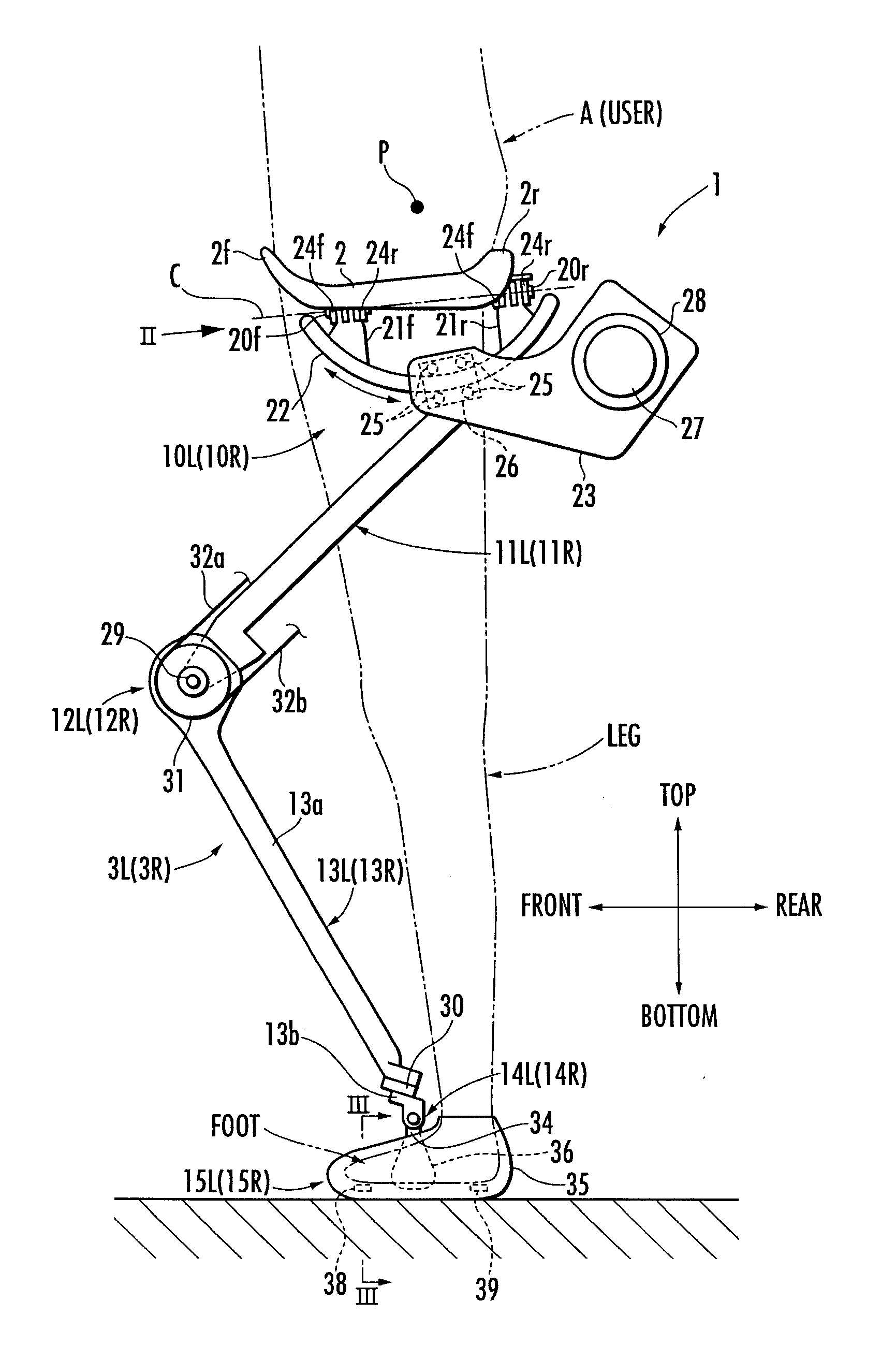
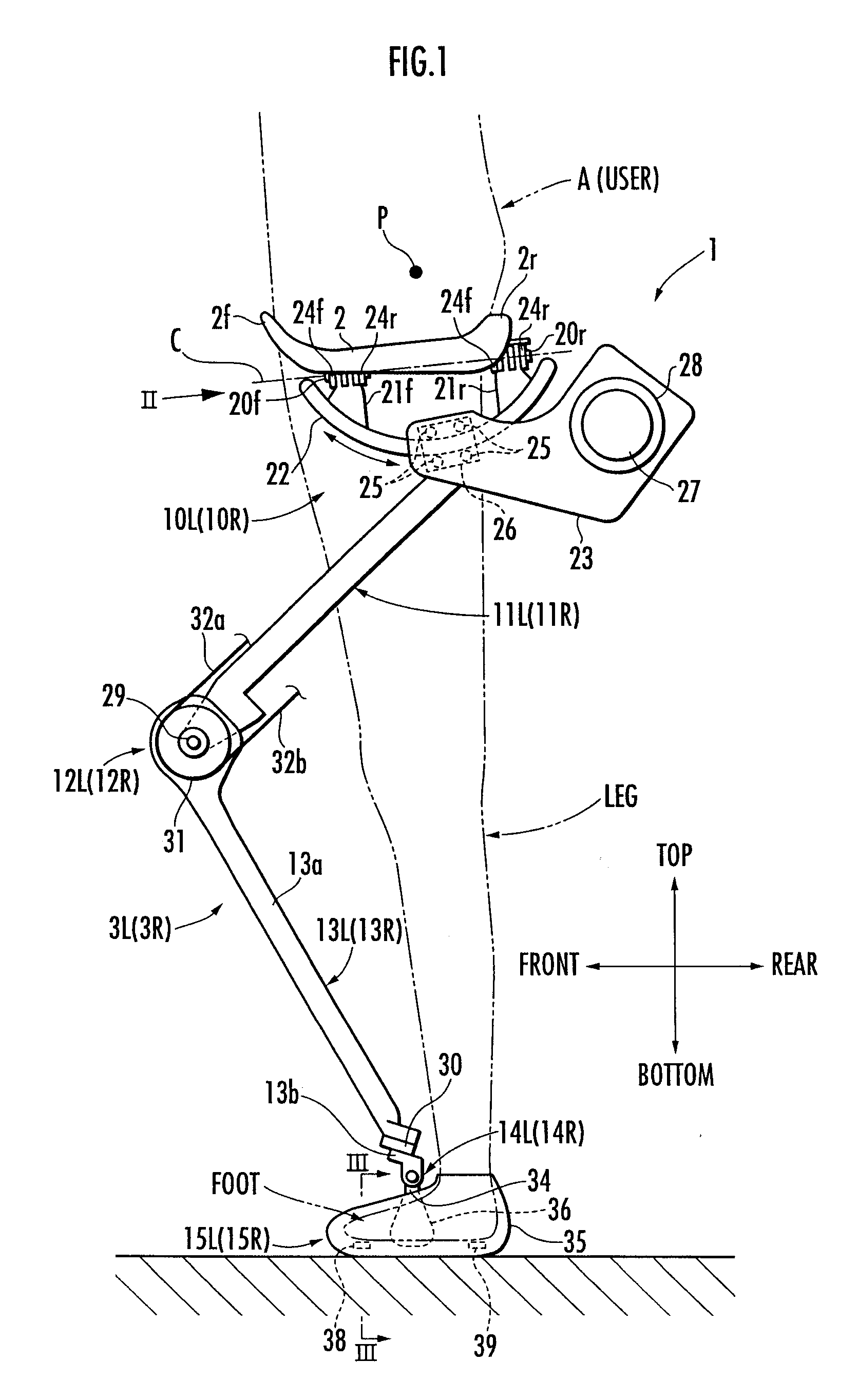
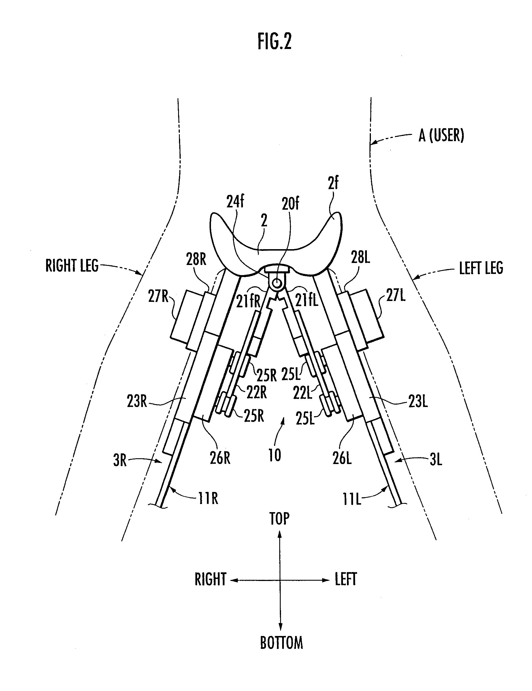
[0097] First, referring to FIG. 1 to FIG. 3, the construction of a walking assist apparatus according to the present embodiment will be explained. FIG. 1 to FIG. 3 show a walking assist apparatus 1 attached to a user A (indicated by a virtual line) and in operation. In this case, the user A in the figure is standing substantially upright. In FIG. 2, however, the user A is at a posture in which his / her both legs are open to the right and left in order to permit easier understanding of the structure of the walking assist apparatus 1.

[0098] Referring to FIG. 1 and FIG. 2, the walking assist apparatus 1 is a weight bearing assist system for supporting a part of the weight of the user A (for making the weight supported by the legs (standing legs) of the user lighter than the weight of himself / herself). The walking assist apparatus 1 includes a seat 2 on which the user A sits...

Example

[0220] Further, in the second embodiment, if the measurement value FRF_R of a negative value is obtained using the table shown in FIG. 14, then a part of the processing shown in FIG. 10 (the processing of the right / left desired lifting force determiner 63) is changed, for example, as follows. If the measurement value FRF_R of a negative value is obtained in S304 of FIG. 10, then the ratio between the two distribution ratios is set to a predetermined ratio established beforehand. For instance, if FRF_R306 and S311. At this time, if, for example, the desired total lifting force, which is an output of S303 shown in FIG. 10, is 200 N, then the outputs of S306 and S311 will be −20 N and 220 N, respectively. A leg for which the provisional measurement value FRF_p that is smaller than the threshold value FRF1 has been obtained (the right leg in the aforesaid example) is determined as a free leg, and the processing for calculating a spring restoring force for the free leg in S305 or S310 is...

Example

[0222] Referring to FIG. 15, in the third embodiment, a foot supporting member 100 is provided inside the annular member 36 of a foot-worn assembly 15. The foot supporting member 100 shaped like a slipper is composed of a plate-like foot sole member 101 (a member like a sole insert of a shoe) that comes in contact with substantially the entire bottom surface of a foot of a user A and an arched member 102 having an approximately semicircular arc-shaped section that is connected to the foot sole member 101. The arched member 102 has its both lower ends connected integrally with both sides of the foot sole member 101. The toe portion of a foot of the user A can be inserted in the arched member 102. With the toe portion inserted therein, the foot is supported on the foot sole member 101. These foot sole member 101 and the arched member 102 are formed of a material, such as a metal or resin, having a predetermined rigidity.

[0223] Further, a tensile strength sensor 103 constituting a fir...


PUM


Abstract

A control device and a control program for a walking assist apparatus set a desired lifting force to act on a user from a seat and distribute the desired lifting force to each leg link of the walking assist apparatus according to the ratios of treading forces of the legs of the user measured on the basis of outputs of force sensors so as to determine the share for each leg link. Then, an actuator of each leg link is controlled to generate a force for the determined share. Thus, a force required for the user to support himself/herself with his/her leg or legs on a floor can be reduced while using a reduced number of parts to be attached to each leg of the user. Moreover, an assist force for achieving such a reduced required force can be properly shared between the leg links associated with the legs of the user.

Description

BACKGROUND OF THE INVENTION [0001] 1. Field of the Invention [0002] The present invention relates to a control device and a control program for a walking assist apparatus adapted to assist a user thereof with his / her walking. [0003] 2. Description of the Related Art [0004] Hitherto, as this type of a walking assist apparatus, there has been known one disclosed in, for example, Japanese Unexamined Patent Application Publication No. H5-329186 (hereinafter referred to as “Patent Document 1”). In the walking assist apparatus (walking aid device) described in this Patent Document 1, supporting members are attached to the thigh, the crus, and the foot of each leg of a user thereof. In the walking assist apparatus, the joints connecting the supporting members are driven by actuators to impart desired motive forces to the user from the walking assist apparatus. [0005] The walking assist apparatus described in Patent Document 1 mentioned above is capable of generating desired motive forces i...

Claims


Application Information

Patent Timeline
IPC IPC(8): A61H3/00A61F5/052
CPCA61H1/00A61H3/00B62D57/032A61H2201/1633B25J9/0006A61H2003/007
Inventor IKEUCHI, YASUSHI
Owner HONDA MOTOR CO LTD
Why Eureka
Try Eureka