
Modular floor tile with nonslip insert system

a floor tile and insert system technology, applied in the field of floor tiles, can solve the problems of not having additional features to increase traction, the top surface of typical interconnected tile systems is often slippery, and the open top surface of typical sports court tile systems has no additional features, so as to achieve the effect of improving traction

Active Publication Date: 2006-12-07
UNITED TECH CORP +1
View PDF70 Cites 68 Cited by
  • Summary
  • Abstract
  • Description
  • Claims
  • Application Information

AI Technical Summary

Benefits of technology

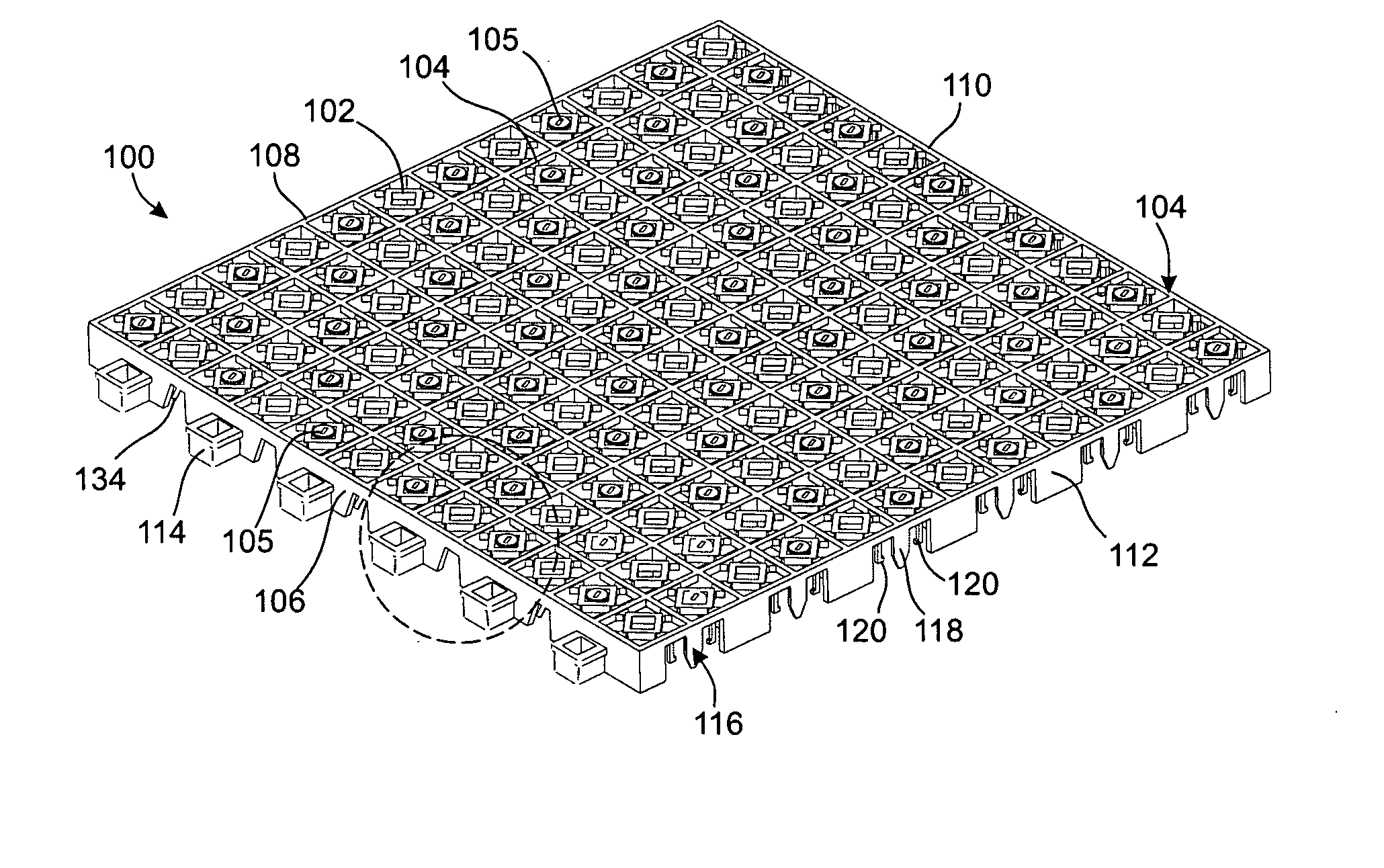
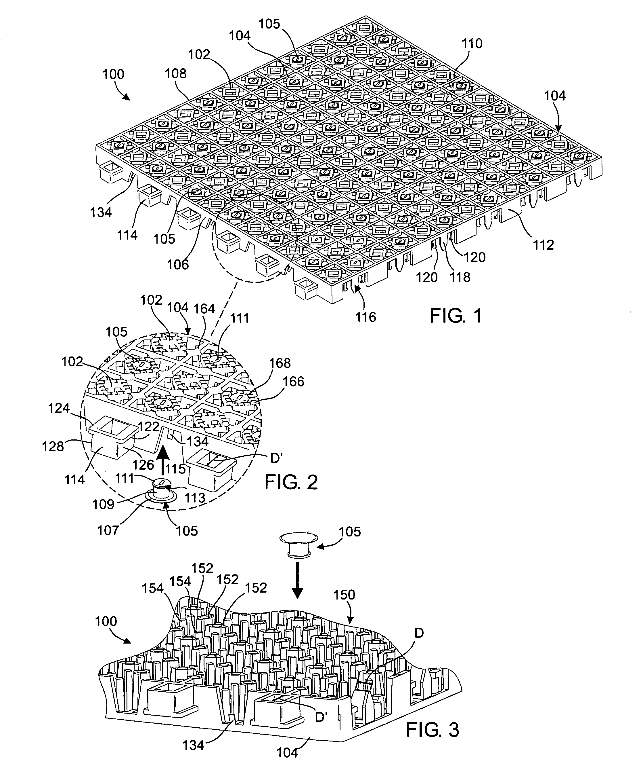
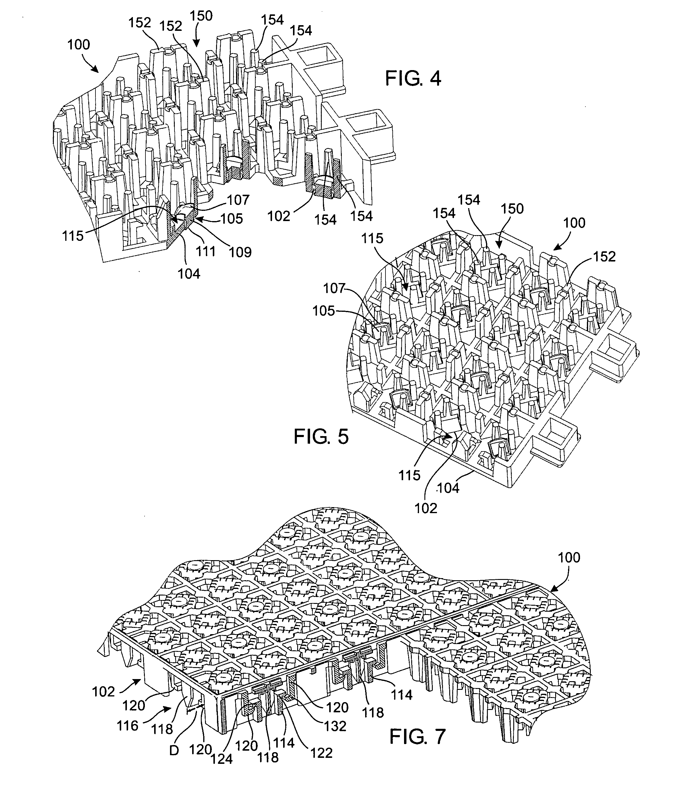
[0005] Some embodiments address the above-described needs and others. In one of many possible embodiments, a modular floor tile is provided. The modular floor tile comprises a first open surface, a plurality of edge surfaces, and an interlocking mechanism for attachment to adjacent tiles. The modular floor tile also includes at least one insert disposed in at least one gap of the first open surface. The insert protrudes from the first open surface and improves traction. The insert may comprise a base and a post extending from the base. The base may be a generally circular base, and the post may comprise a generally cylindrical post extending from the base. According to some embodiments, a lip extends radially from an end of the generally cylindrical post. The insert may comprises a base, a compressible column, and a pad. A force on the pad causes the compressible column to compress, wherein the pad may be forced to a generally flush arrangement with the first open surface without displacing the base.
[0010] Another aspect provides a method of increasing traction of a modular floor. The method comprises providing an interlocking modular tile having a first open surface, inserting an insert into a surface of the interlocking modular tile, and protruding the insert from the first open surface. Inserting may further comprise fitting the insert into a nest by an interference fit. Inserting may also comprise pressing the insert through a gap in the first open surface in a first direction

Problems solved by technology

However, the top surface of typical interconnected tile systems is often slippery.
The open top surfaces of typical sports court tile systems, however, have no additional features to increase traction.

Method used


Image

  • Modular floor tile with nonslip insert system
  • Modular floor tile with nonslip insert system
  • Modular floor tile with nonslip insert system

Examples


Embodiment Construction

[0026] As mentioned above, typical modular flooring comprises solid or open top surfaces that tend to be slippery. The slippery surfaces compromise the footing of users, especially sports court users that tend to start and stop abruptly. The typical modular floor offers less than ideal traction to dance, sport, pedestrian, and other traffic. The principles described herein present methods and apparatus that provide better traction and more flexibility than previous flooring systems. However, the application of the principles described herein is not limited to the specific embodiments shown. The principles described herein may be used with any flooring system. Moreover, although certain embodiments shown incorporate multiple novel features, the features may be independent and need not all be used together in a single embodiment. Tiles and flooring systems according to principles described herein may comprise any number of the features presented. Therefore, while the description below...


PUM

PropertyMeasurementUnit
Lengthaaaaaaaaaa
Thicknessaaaaaaaaaa
Forceaaaaaaaaaa

Abstract

The principles described herein provide floor tiles and modular floors. The floor tiles include inserts that increase traction. The inserts may be removable and protrude from a top surface of the floor tiles. The tiles may include a locking system that allows adjacent tiles to interlock, while also permitting a predetermined amount of lateral sliding relative to one another. The modular tiles may be injection molded and the inserts may comprise an elastomer. The floor tiles may also provide four layers of traction, providing more sure footing than previous flooring systems.

Description

RELATED APPLICATIONS [0001] This is a continuation-in-part of U.S. patent application Ser. No. 11 / 143,337 filed 2 Jun. 2005 and entitled “Modular Floor Tile System with Sliding Lock.”TECHNICAL FIELD [0002] This relates generally to floor tiles, and more particularly to nonslip modular floor systems. BACKGROUND [0003] Floor tiles have traditionally been used for many different purposes, including both aesthetic and utilitarian purposes. For example, floor tiles of a particular color may be used to accentuate an object displayed on top of the tiles. Alternatively, floor tiles may be used to simply protect the surface beneath the tiles from various forms of damage. Floor tiles typically comprise individual panels that are placed on the ground either permanently or temporarily depending on the application. A permanent application may involve adhering the tiles to the floor in some way, whereas a temporary application would simply involve setting the tiles on the floor. Some floor tiles ...

Claims


Application Information

Patent Timeline
IPC IPC(8): E04F13/08
CPCE01C5/20E01C11/24E01C2201/16E01C2201/12E01C13/045
Inventor MOLLER, JORGEN J. JR.
Owner UNITED TECH CORP
Learn More