Gas turbine and a method for controlling a gas turbine

a technology of gas turbine and control method, which is applied in the direction of turbine/propulsion engine ignition, engine starter, machine/engine, etc., can solve the problems of transients being associated with peak emissions, quantity is not stable,

Inactive Publication Date: 2006-12-07
VOLVO AERO CORP
View PDF6 Cites 80 Cited by
  • Summary
  • Abstract
  • Description
  • Claims
  • Application Information

AI Technical Summary

Benefits of technology

[0007] A first object of the invention is to provide a gas turbine that creates the prerequisites for accurate metering of fuel to the combustion chamber, and especially during transient operation.
[0011] A second object of the invention is to provide a method for controlling a gas turbine that gives an accurate metering of fuel to the combustion chamber, especially during transient operation.

Problems solved by technology

These quantities, however, are not stable in the case of rapid transients.
Such transients are furthermore usually associated with peak emissions since known solutions do not provide sufficiently rapid feedback control.

Method used


Image

  • Gas turbine and a method for controlling a gas turbine
  • Gas turbine and a method for controlling a gas turbine
  • Gas turbine and a method for controlling a gas turbine

Examples


Embodiment Construction

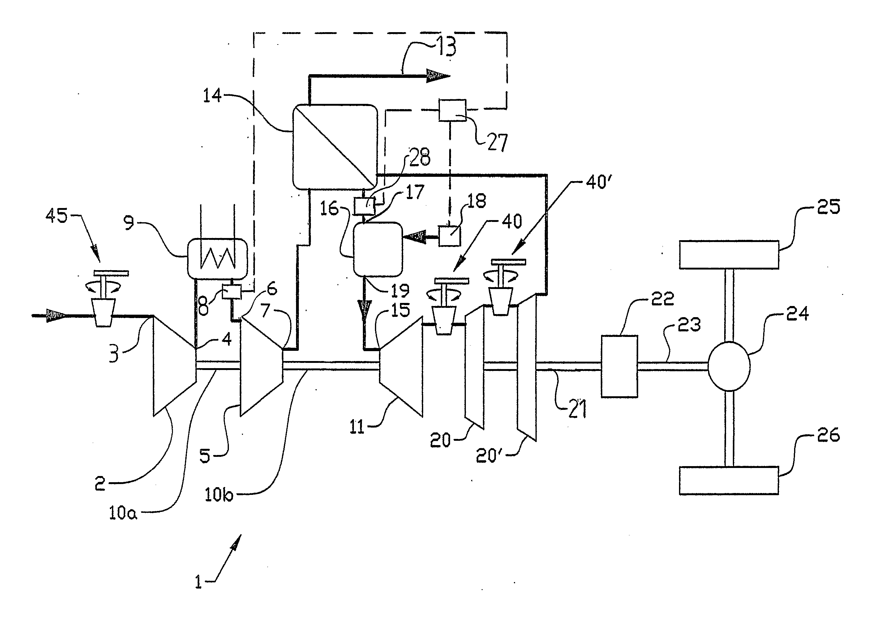
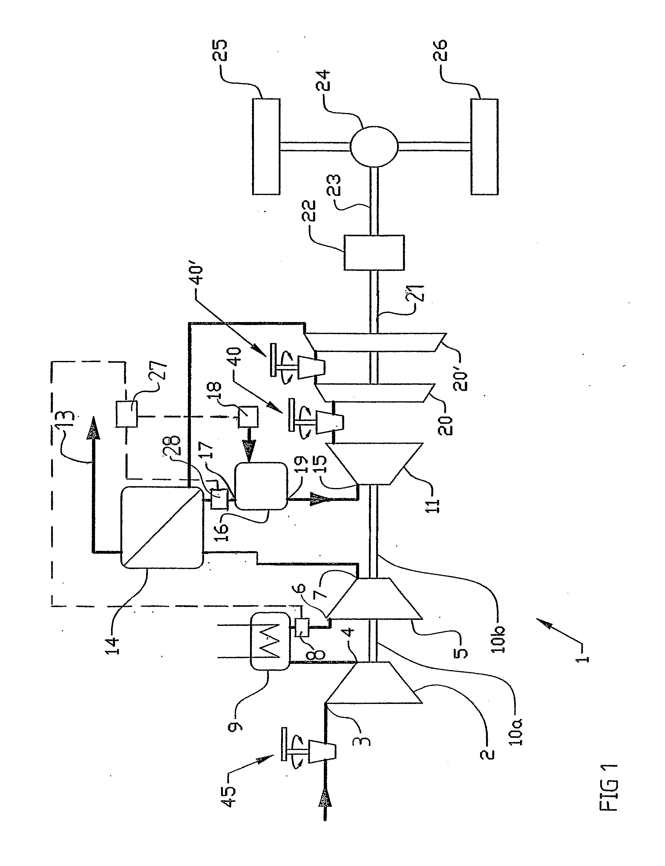
[0017]FIG. 1 shows a schematic diagram of a twin-shaft gas turbine 1 configured according to a first embodiment of the invention. This is a suitable construction for a gas turbine with low-emission combustion chamber in an application in which transients occur. The gas turbine 1 comprises (includes, but is not necessarily limited to) a first compressor 2 having a first compressor inlet 3 and a first compressor outlet 4 together with a second compressor 5 having a second compressor inlet 6 and a second compressor outlet 7. The compressor inlet 3 of the first compressor 2 is open to the atmosphere via an air filter (not shown). An intercooler 9, the function of which is to cool the air compressed by the first compressor 2 before a further pressure increase occurs in the second compressor 5, is arranged between the compressor outlet 4 of the first compressor 2 and the compressor inlet 6 of the second compressor 5. The intercooler 9 is coupled to a separate cooling system (not shown).

[...


PUM


Abstract

Method and arrangement for providing and controlling a gas turbine (1) at least one turbine (11, 20, 20′), at least one compressor (2, 5) driven by the turbine and a combustion chamber (16) arranged between the compressor and the turbine in the airflow path. The gas turbine includes devices (8) for direct measurement of the air mass flow at a position upstream of the combustion chamber in the airflow path, with the aim of regulating the quantity of fuel that is delivered to the combustion chamber (16) on the basis of the measured air mass flow.

Description

CROSS-REFERENCE TO RELATED APPLICATIONS [0001] The present application is a continuation patent application of International Application No. PCT / SE2004 / 000856 filed 2 Jun. 2004 which is published in English pursuant to Article 21(2) of the Patent Cooperation Treaty and which claims priority to Swedish Application No. 0301645-8 filed 5 Jun. 2003. Said applications are expressly incorporated herein by reference in their entireties.BACKGROUND OF THE INVENTION [0002] The present invention relates to a gas turbine. The invention further relates to a method for controlling a gas turbine. The gas turbine includes at least one turbine, at least one compressor driven by the turbine and a combustion chamber arranged between the compressor and the turbine in the airflow path. The gas turbine is designed for compressing the gas in the compressor, heating the compressed gas in the combustion chamber and expansion of the heated gas in the turbine. [0003] Gas turbines are used, for example, as eng...

Claims


Application Information

Patent Timeline
Patent Type & Authority Applications(United States)
IPC IPC(8): F02C9/28F01D17/16F02C3/10F02C6/20F02C9/16F02C9/50
CPCF01D17/162F02C3/10F02C6/20F05D2270/303F02C9/28F02C9/50F02C9/16
Inventor SUNDIN, LARS
Owner VOLVO AERO CORP
Why Eureka
Try Eureka