Steering device

Inactive Publication Date: 2006-12-07
NSK LTD
View PDF10 Cites 15 Cited by
  • Summary
  • Abstract
  • Description
  • Claims
  • Application Information

AI Technical Summary

Benefits of technology

[0024] Various implementations may include one or more the following advantages. For example, in the steering device of the invention, at the circular outer circumference of a keylock collar, which is spaced at its axial position with respect to a polygonal inner circumference to be press-fitted on the outer circumference of a steering shaft, either ridges to bulge radially outward from the circular outer circumference or bottomed grooves recessed radially inward from that circular outer circumference, and the leading end portion of a lock key is engaged with the ridges or bottomed grooves. As a result, the numerous ridges or bottomed grooves can be formed at the circular outer circumference of the keylock collar, so that the steering device can be easily applied to an electric steering lock device, in which the insertion/retraction of the lock key is performed by an actuator such as a motor.
[0025] In the steering device of the invention, at the circular outer circumference of a keylock collar, which is at the same axial position as that of a polygonal inner circumference to be press-fitted on the outer circumference of a steering shaft, either ridges to bulge radially outward from the circular outer circumference or bottomed grooves recessed radially inward from that circular outer c

Problems solved by technology

However, when the steering wheel is forcibly rotated with the steering shaft being locked, the lock key may be broken to lose the function of the steering lock device thereby to lose the function as the theft preventing device.
In the steering device of Patent Document 1, however, the outer circumference of the keylock collar is formed into a noncircular shape similar to that of the inner circumference and the thickness of the keylock column is thin, so that

Method used


Image

  • Steering device
  • Steering device
  • Steering device

Examples


embodiment 1

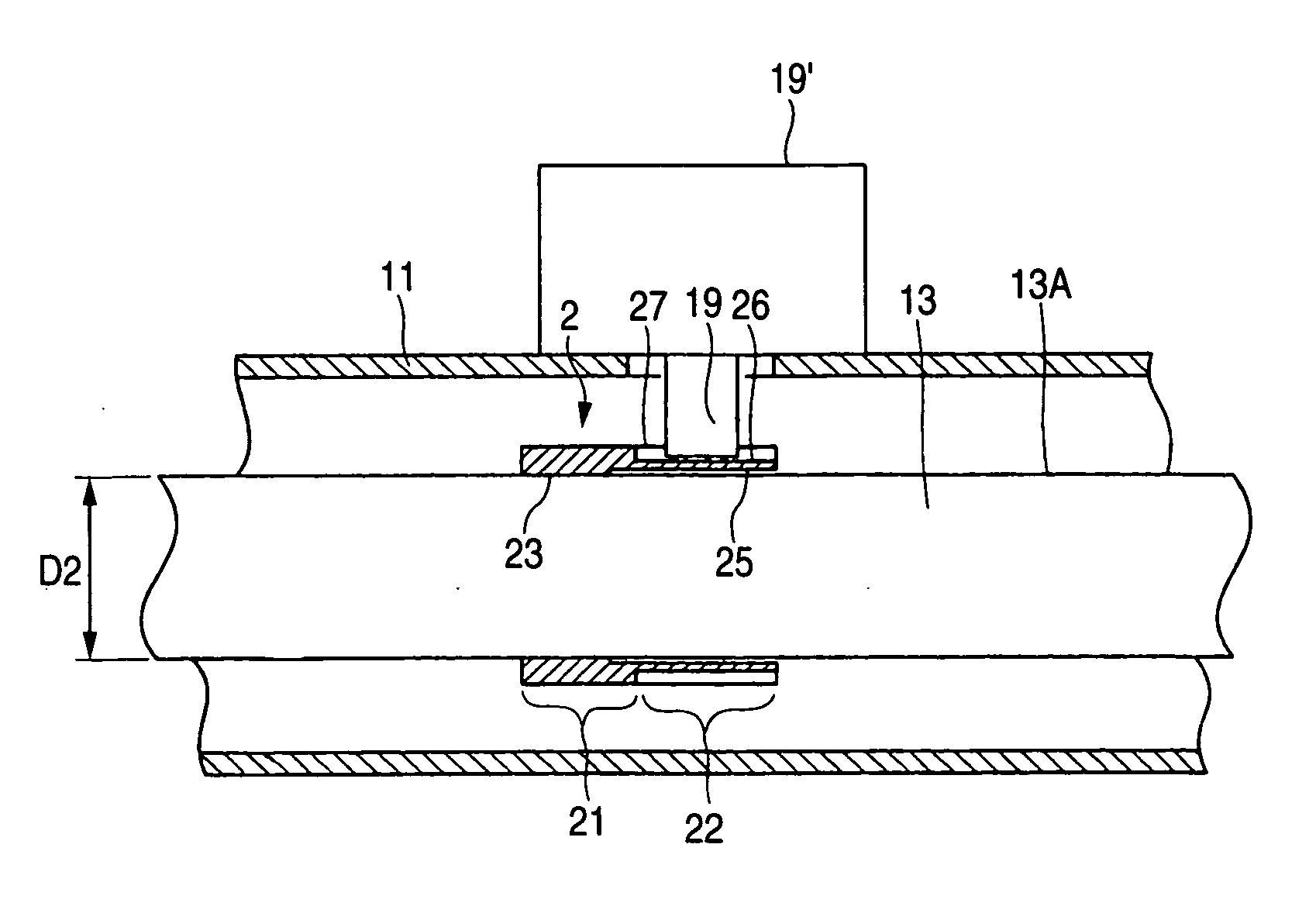
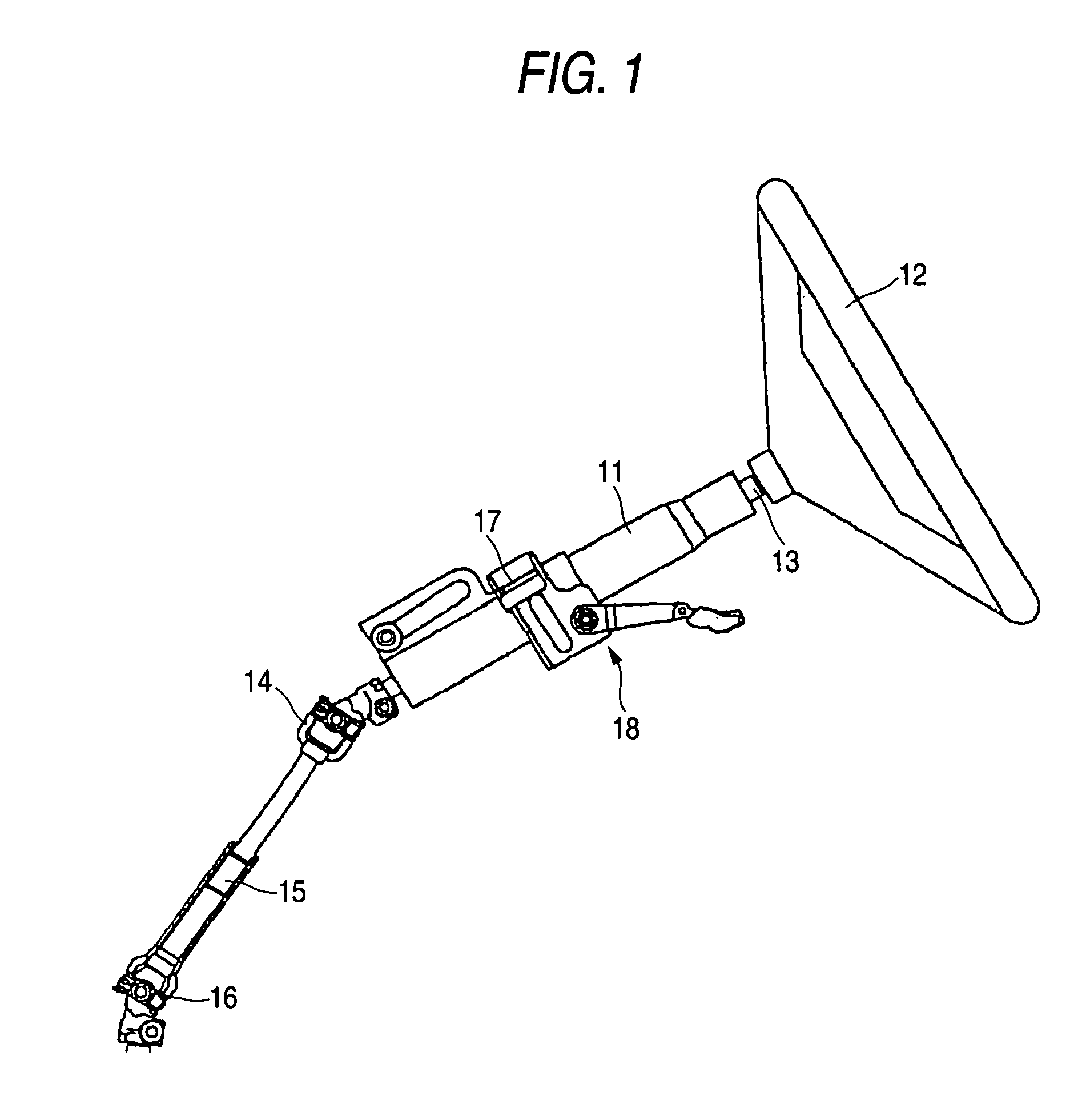
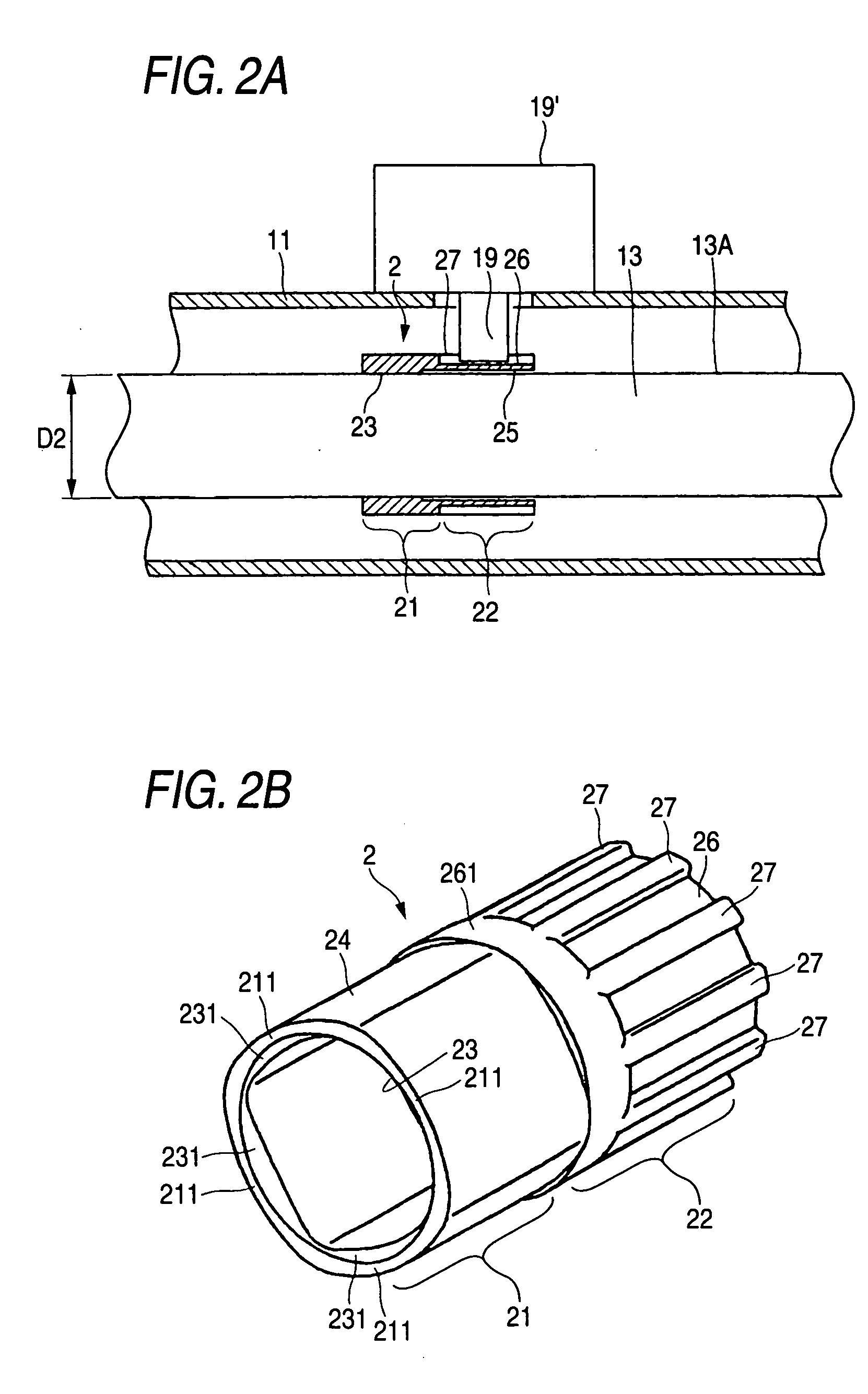
[0067]FIG. 1 is a side elevation showing the entirety of a steering device of the invention. FIG. 2A is an enlarged longitudinal section of a fitting portion of a steering shaft and a keylock collar of Embodiment 1 of the invention, and FIG. 2B is a perspective view of the single keylock collar of FIG. 2A. FIG. 3A is a front elevation of the single keylock collar of FIG. 2B; FIG. 3B is a left side view of FIG. 3A; and FIG. 3C is a section A-A of FIG. 3B. FIG. 4A is a section B-B of FIG. 3A, and FIG. 4B is a section C-C of FIG. 3A.

[0068] In a column 11, as shown in FIG. 1, there is rotatably borne a steering shaft 13, which fits a steering wheel 12 on the back side of a vehicle body. An extendible intermediate shaft 15 is connected to the body front side of the steering shaft 13 through an upper universal joint 14.

[0069] To the lower end of that intermediate shaft 15, there is connected through a lower universal joint 16 the not-shown rack-and-pinion steering gear, to which the whe...

embodiment 2

[0085] Embodiment 2 of the invention is described in the following. FIG. 5A is an enlarged longitudinal section of a fitting portion of a steering shaft and a keylock collar of Embodiment 2 of the invention, and FIG. 5B is a perspective view of the single keylock collar of FIG. 5A. FIG. 6A is a front elevation of the single keylock collar of FIG. 5B, and FIG. 6B is a left side view of FIG. 6A. The following description is made exclusively on constitutional portions and actions different from those of Embodiment 1 while omitting the overlapped portions. Moreover, the description is made by designating the parts identical to those of Embodiment 1 by the common reference numerals.

[0086] In Embodiment 2, the square cylinder portion 21 to be press-fitted on the steering shaft 13 and the cylindrical portion 22 to have the ridges 27 are formed at the identical axial positions. As shown in FIG. 5A, the keylock collar 3 is press-fitted and fixed on the outer circumference 13A of the steerin...

embodiment 3

[0095] Embodiment 3 of the invention is described in the following. FIG. 7A is a perspective view of the single keylock collar of Embodiment 3 of the invention; FIG. 7B is a front elevation of the single keylock collar of FIG. 7A; and FIG. 7C is a left side view of FIG. 7B. The following description is made exclusively on constitutional portions and actions different from those of Embodiment 1 and Embodiment 2 while omitting the overlapped portions. Moreover, the description is made by designating the parts identical to those of Embodiment 1 and Embodiment 2 by the common reference numerals.

[0096] In Embodiment 3, ridges are formed on the outer circumference of the keylock collar, which has both its inner and outer circumferences formed into squares. As shown in FIG. 7, an inner circumference 43 of the keylock collar 4 is formed into a curved square shape. Specifically, the four sides 411, 411, 411 and 411 of the inner circumference 43 are formed to have a larger radius of curvatur...


PUM


Abstract

A keylock collar 2 is constituted to include a square cylinder portion 21 on its body front side half and a cylindrical portion 22 on its body back side half. The circular outer circumference 26 of the cylindrical portion 22 has eleven ridges 27 formed at an angularly equal spacing to bulge radially outward. When an ignition key is turned to a lock position and pulled from the keyhole, a lock key 19 is protruded toward the axis of a steering shaft 13. As a result, the leading end of the lock key 19 comes into engagement between the side faces 271 and 271 of the adjoining ridges 27 and 27 of the keylock collar 2 so that the steering shaft 13 is fixed with respect to a column 11 thereby to block the rotation of the steering shaft 13.

Description

BACKGROUND OF THE INVENTION [0001] The present disclosure relates to a steering device and, more particularly, to a steering device having a steering lock device for locking a steering wheel irrotationally to prevent theft of a vehicle after an ignition key is turned to a lock position and extracted from a keyhole. [0002] In the steering device having the steering lock device, when the ignition key is turned to the lock position and extracted from the keyhole, the lock key protrudes toward the axis of a steering shaft. As a result, the leading end of the lock key comes into engagement with the keylock hole of the keylock collar fixed on the outer circumference of the steering shaft so that the steering shaft is fixed with respect to an outer column thereby to block the rotation of the steering shaft. [0003] However, when the steering wheel is forcibly rotated with the steering shaft being locked, the lock key may be broken to lose the function of the steering lock device thereby to ...

Claims


Application Information

Patent Timeline
IPC IPC(8): B60R25/02B60R25/021
CPCB60R25/0211B60R25/02107Y10T70/5664
Inventor YAMADA, JUNMORIYAMA, SEIICHI
Owner NSK LTD
Why Eureka
Try Eureka