
Mounting structure of resin molded part

Inactive Publication Date: 2006-12-07
TOYODA GOSEI CO LTD
View PDF5 Cites 7 Cited by
  • Summary
  • Abstract
  • Description
  • Claims
  • Application Information

AI Technical Summary

Benefits of technology

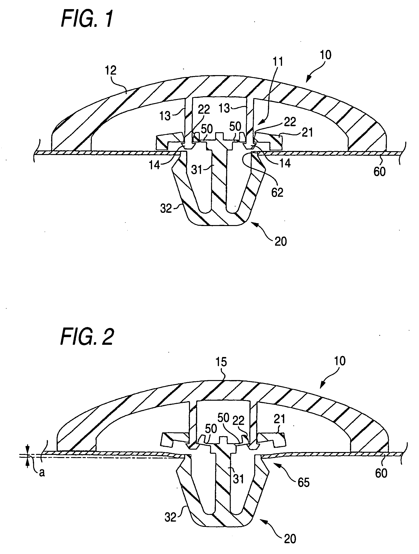
[0018] While it may be provided on any of the seat portion, the leg portion and the connecting portion, the deformable portion is preferably provided on the seat portion or the connecting portion. This is because since the seat portion is situated at an end portion of the clip and the connecting portion is situated at an end portion of the resin molded part, the deformable portion can easily be formed on the seat portion and the connecting portion. In the event that the deformable portion is provided on the seat portion, the deformable portion is preferably formed on the seat portion at the boundary portion with the leg portion. This is because a sufficient portion is secured which is joined to the resin molded part so that the resin molded part is fixed to the clip stably. The deformable portion is preferably formed thin or made from a soft material. This is because the deformable portion is made to deform easily.
[0019] In the event that the deformable portion is provided on the connecting portion, the connecting portion is preferably formed into a rib shape in such a manner as to project from a surface of the resin molded part. By forming the connecting portion into the rib shape, a function to reinforce the resin molded part can be imparted to the connecting portion. In addition, by forming the connecting portion into the rib shape, a contact area between the other portion than the connecting portion of the resin molded part (hereinafter, the portion being referred to a main body portion) and the connecting portion can be reduced. Consequently, the deformation of the deformable portion is made difficult to be transmitted to the main body portion, whereby the deformable portion can be made to deform while the deformation of the resin molded part is being prevented.

Problems solved by technology

However, when the resin molded part is made to deflect and deform, since a front surface of the resin molded part is deformed into a recess shape, the front surface of the resin molded part deforms.
Consequently, in also this event, the problem remains unsolved where the appearance of the resin molded part is deteriorated by the deformation of the resin molded part.
Consequently, the overall deformation of the resin molded part cannot be suppressed, and when the degree of recess at the engaged region is large, a deformation is caused in the resin molded part at a position spaced apart from the elastic portion.
Thus, the problem still remains unsolved where the appearance of the resin molded part is deteriorated by the deformation thereof.

Method used


Image

  • Mounting structure of resin molded part
  • Mounting structure of resin molded part
  • Mounting structure of resin molded part

Examples


embodiments

Embodiment 1

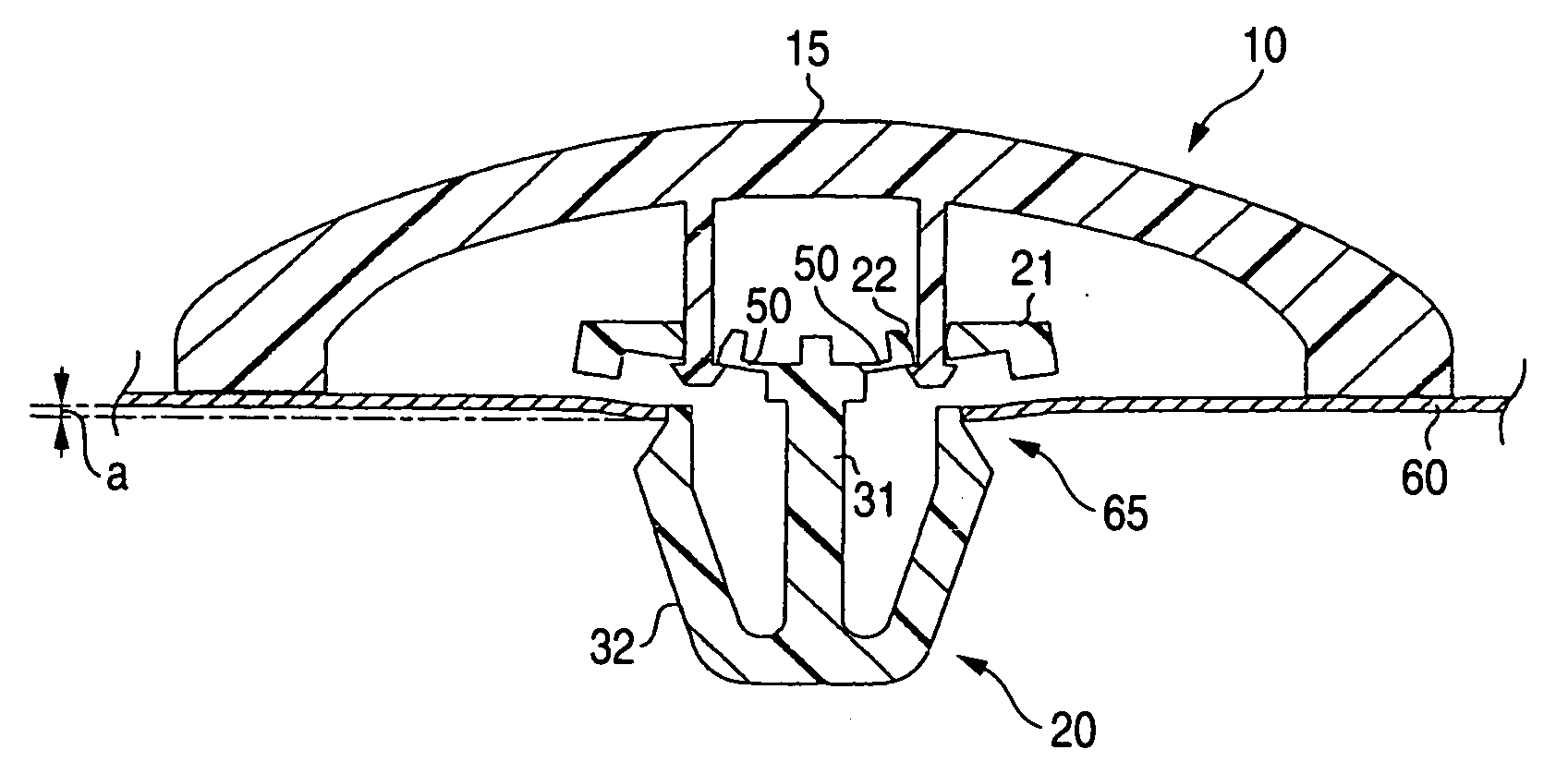
[0034] A resin molded part mounting structure according to Embodiment 1 includes a side molding as a resin molded part and a clip. A mating member is a body panel of a motor vehicle. The resin molded part mounting structure of Embodiment 1 includes the configuration (1). Sectional views are shown in FIGS. 1 and 2 which exemplarily show the resin molded part mounting structure of Embodiment 1. FIG. 1 shows how the resin molded part mounting structure is fixed to a mating member which is formed level. FIG. 2 shows how the resin molded part mounting structure is fixed to a mating member which is recessed at an engaged region thereof.

[0035] In the resin molded part mounting structure of Embodiment 1, a resin molded part 10 is a long material made from a resin. As shown in FIG. 1, a connecting portion 11 is formed on a rear surface of the resin molded part 10. The resin molded part 10 is made up of the connecting portion 11 and a main body portion 12 which is made up of the...

embodiment 2

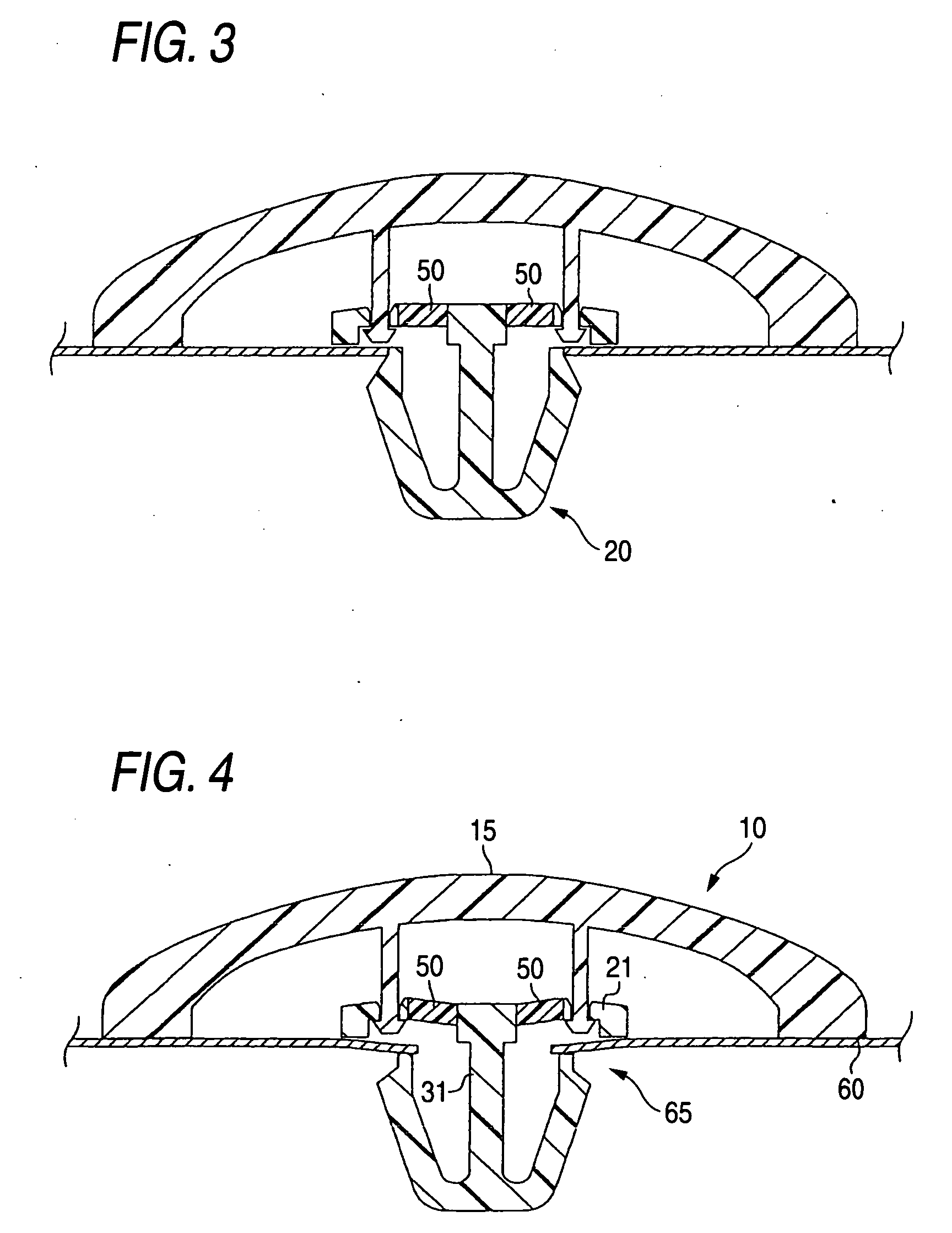
[0043] A resin molded part mounting structure according to Embodiment 2 includes the configuration (2). The resin molded part mounting structure of Embodiment 2 is similar to Embodiment 1 except that a deformable portion is made from a soft material. Cross sections are shown in FIGS. 3 and 4 which exemplarily show the resin molded part mounting structure of Embodiment 2. FIG. 3 shows how the resin molded part mounting structure of Embodiment 2 is fixed to a mating member which is formed level. FIG. 4 shows how the resin molded part mounting structure of Embodiment 2 is fixed to a mating member whose engaged region is recessed.

[0044] In the resin molded part mounting structure of Embodiment 2, a deformable portion 50 of a clip 20 is made from a soft material such as TPEE (polyester-based elastomer) or rubber added POM (polyoxymethylene). The remaining portion of the clip 20 which excludes the deformable portion 50 is made from PA (polyamide) or POM. The portion of the clip which exc...

embodiment 3

[0046] A resin molded part mounting structure of Embodiment 3 is an example where a seat portion of a clip is formed separately from the other portion of the clip for subsequent integration with each other. The resin molded part mounting structure of Embodiment 3 includes the configuration (1). Cross sections are shown in FIGS. 5 and 6 which exemplarily show the resin molded part mounting structure of Embodiment 3. FIG. 5 shows how the resin molded part mounting structure of Embodiment 3 is fixed to a mating member which is formed level. FIG. 6 shows how the resin molded part mounting structure of Embodiment 3 is fixed to a mating member whose engaged region is recessed.

[0047] In the resin molded part mounting structure of Embodiment 3, a clip 20 is made up of a clip body 25 which is, in turn, made up of a leg portion 31 and an engaging portion 32 and a seat portion 21, the clip body 25 and the seat portion 21 being formed as separate pieces. The seat portion 21 is formed into a sh...


PUM


Abstract

There is provided a resin molded part mounting structure in which a resin molded part is fixed to a mating member via a clip, wherein a connecting portion is provided on the resin molded part, wherein the clip is made up of a seat portion adapted to be joined to the connecting portion and a clip body which has a leg portion which extends from the seat portion and an engaging portion which is formed at a distal end of the leg portion, and wherein a deformable portion which deforms to extend a distance between the resin molded part and the mating member is provided on at least one of the seat portion, the leg portion and the connecting portion.

Description

BACKGROUND OF THE INVENTION [0001] 1. Field of the Invention [0002] The present invention relates to a resin molded part mounting method for fixing a resin molded part to a mating member. A resin molded part mounting structure of the invention can be used as, for example, a mounting structure for fixing a side molding, which is a resin molded part, to a body panel of a motor vehicle, which is a mating member. [0003] 2. Related Art [0004] As resin molded parts that are fixed to a mating member via clips, there are known an automotive decorative element such as a side molding 20, a rocker molding 202 and a door molding 203, which are shown in FIG. 11A, and a clouding panel 204, which is shown in FIG. 11B. A side molding, a clip and a body panel, which are common, are shown in FIG. 12 for description of a common resin molded part mounting structure, which will be made as below. [0005] A resin molded part mounting structure shown in FIG. 12 includes a side molding as a resin molded part...

Claims


Application Information

Patent Timeline
IPC IPC(8): G01N3/24
CPCB60R13/0206B60R13/04F16B21/086F16B21/075F16B5/123
Inventor MAEDA, HIDETOKAWASHIMA, DAIICHIROTAKEDA, KAZUO
Owner TOYODA GOSEI CO LTD
Learn More