Electromagnetically driven valve
a technology of electric drive and valve element, which is applied in the direction of valve operating means/release devices, non-mechanical valves, machines/engines, etc., can solve the problem of inability to achieve the driving force sufficient to move the valve element to the fully open position or to the fully closed position, and achieve the effect of unnecessary power consumption
- Summary
- Abstract
- Description
- Claims
- Application Information
AI Technical Summary
Benefits of technology
Problems solved by technology
Method used
Image
Examples
first embodiment
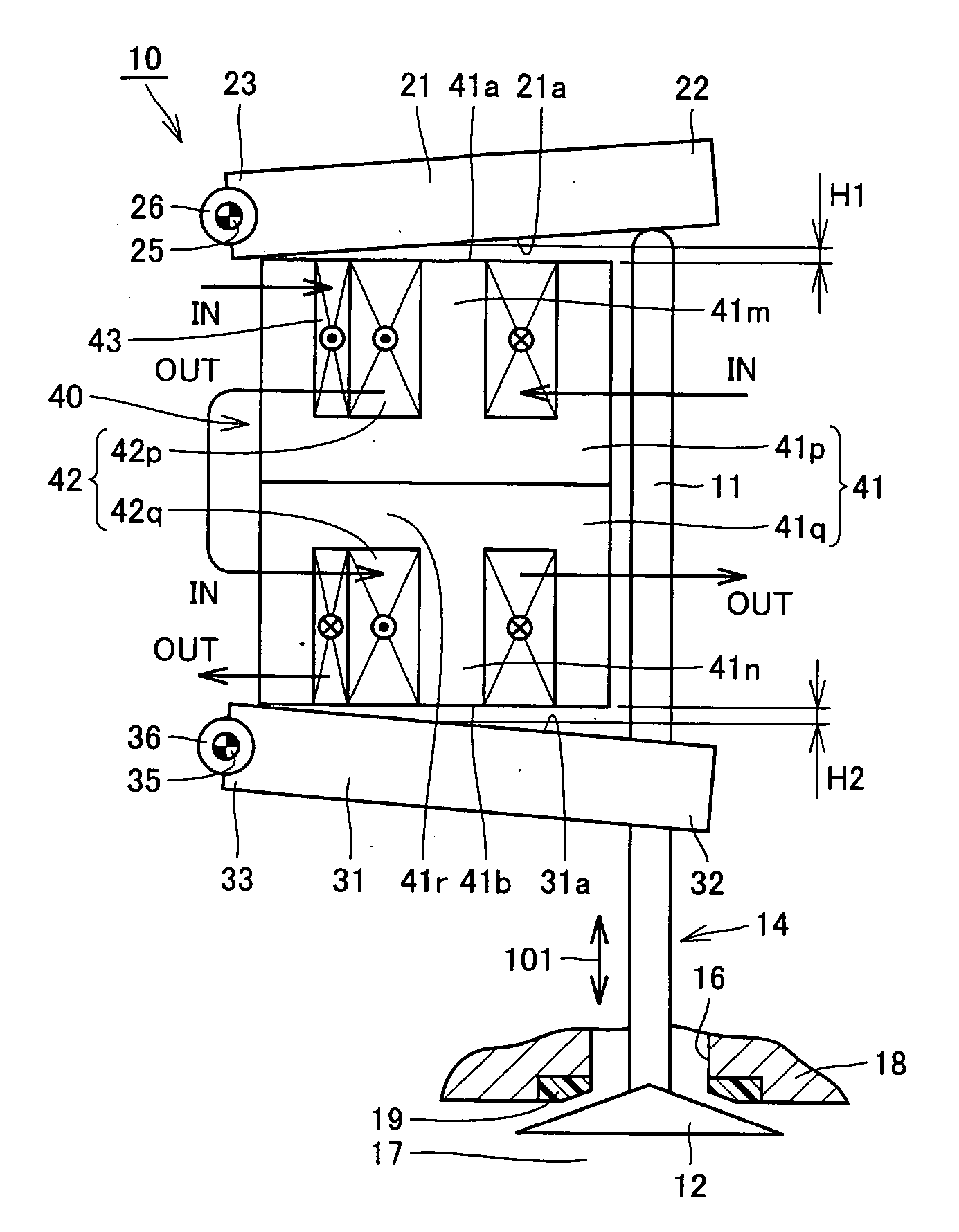
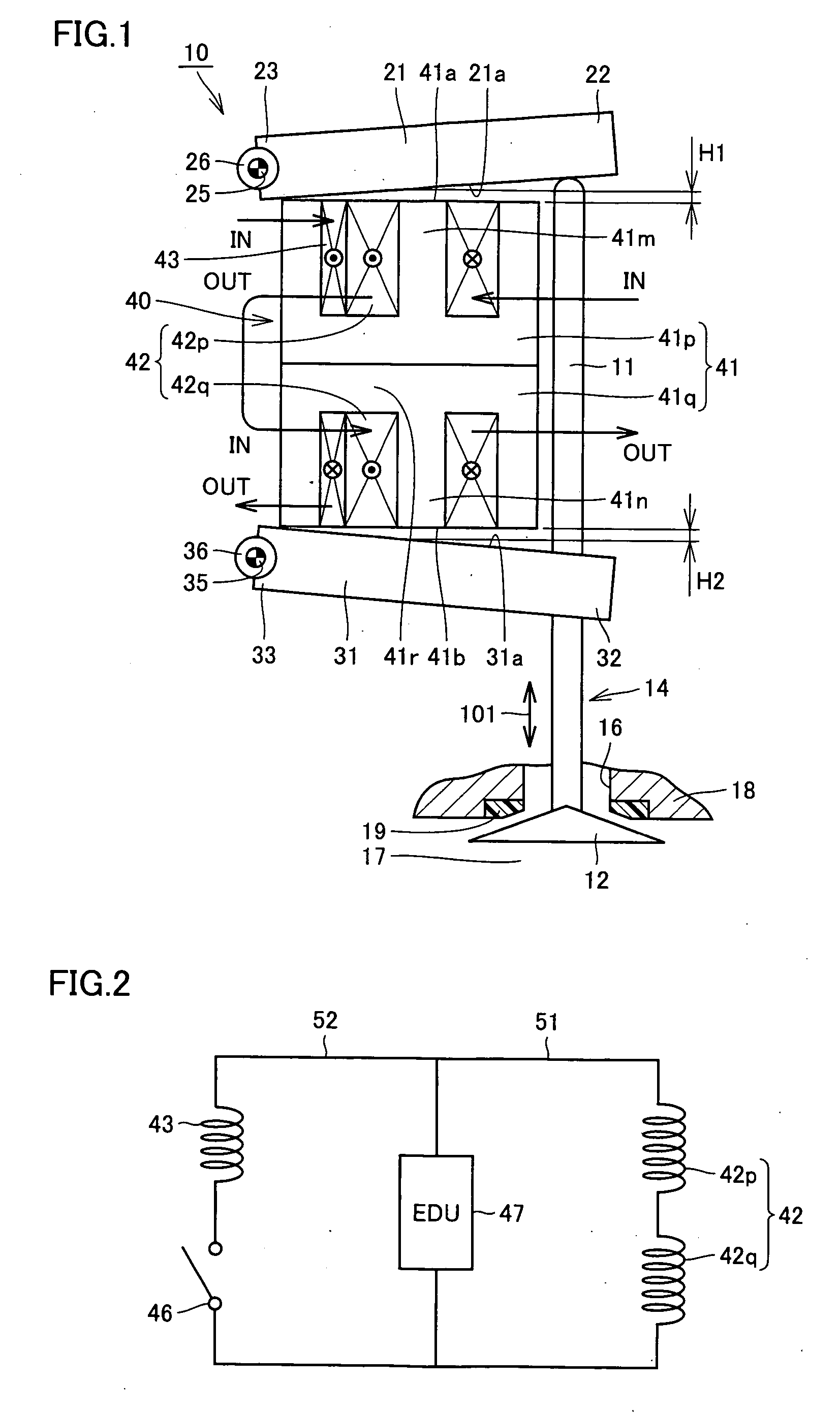
[0024]FIG. 1 shows an electromagnetically driven valve according to a first embodiment of the present invention. The electromagnetically driven valve according to the present embodiment implements an engine valve (an intake valve or an exhaust valve) in an internal combustion engine such as a gasoline engine or a diesel engine. In the present embodiment, description will be given assuming that the electromagnetically driven valve implements an exhaust valve, however, the electromagnetically driven valve is similarly structured also when it implements an intake valve.
[0025] Referring to FIG. 1, an electromagnetically driven valve 10 is a rotary drive type electromagnetically driven valve, driven by cooperation of magnetic force and elastic force. As a motion mechanism for the electromagnetically driven valve, a parallel link mechanism is adopted.
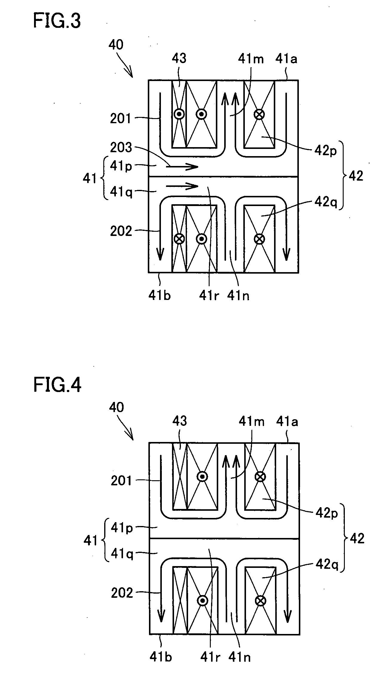
[0026] Electromagnetically driven valve 10 includes a driven valve 14, a valve-opening side moving element 21 and a valve-closing side mov...
second embodiment
[0049]FIG. 5 shows an electromagnetically driven valve in a second embodiment of the present invention. The electromagnetically driven valve in the present embodiment includes, in comparison with electromagnetically driven valve 10 in the first embodiment, partially the same structure. In the following, description of the overlapping structure will not be given.
[0050] Referring to FIG. 5, in the present embodiment, valve-opening side moving element 21 and valve-closing side moving element 31 shown in FIG. 1 are not provided, and a moving element 61 is provided instead. Moving element 61 is formed from a magnetic material, and has a support portion 63, a coupling portion 62 and a surface 61a, corresponding to support portion 23, coupling portion 22 and surface 21a of valve-opening side moving element 21 shown in FIG. 1. Moving element 61 further has a surface 61b opposite to surface 61a. At support portion 63, a central axis 65 to be the center of the oscillating movement of moving ...
PUM
 Abstract
Description
Claims
Application Information
 - R&D
- Intellectual Property
- Life Sciences
- Materials
- Tech Scout
- Unparalleled Data Quality
- Higher Quality Content
- 60% Fewer Hallucinations
Browse by: Latest US Patents, China's latest patents, Technical Efficacy Thesaurus, Application Domain, Technology Topic, Popular Technical Reports.
© 2025 PatSnap. All rights reserved.Legal|Privacy policy|Modern Slavery Act Transparency Statement|Sitemap|About US| Contact US: help@patsnap.com


