Buoyancy type drain trap

a drain trap and buoyancy technology, applied in the direction of valve details, thin material handling, valve arrangement, etc., can solve the problems of difficult uncertain opening and closing of the valve seat, and difficulty in opening and closing the valve seat, so as to improve the buoyancy, reduce the weight of the float, and discharge the drain water smoothly

Inactive Publication Date: 2006-12-07
FUKUHARA KK
View PDF0 Cites 14 Cited by
  • Summary
  • Abstract
  • Description
  • Claims
  • Application Information

AI Technical Summary

Benefits of technology

[0014] The drain trap of the present invention, which is constructed as described above provides the following effects.
[0015] First, in a drain water discharging method which makes it possible to discharge drain water having flowed into the case accommodating the float by buoyancy acting on the float, when the inner diameter of the valve connected to the outlet port formed in the case is enlarged in order to increase the discharge flow rate at the valve, movement of a rubber valve seat when opening the valve is facilitated by adding some force to enhance the buoyancy or by reducing a weight of the float itself, whereby it is possible to discharge drain water smoothly.
[0016] Second, even in a case where an attempt is made to enlarge the inner diameter of the valve in order to increase the flow rate at the outlet port, the movement of the rubber valve seat when opening the valve is facilitated by positioning the coil spring or the compression spring between the case and the float as a device for adding some force, whereby it is possible to discharge drain water smoothly.
[0017] Third, even in a case where an attempt is made to enlarge the inner diameter of the valve in order to increase the flow rate at the outlet port, the movement of the rubber valve seat when opening the valve is facilitated by arranging, as the auxiliary buoyancy device, the coil spring between the adjustment screw and the arm so as to be integrated with the adjustment screw and the valve while holding the case main body and the float bracket, with the compression force of the coil spring being adjustable by varying the thickness of an adjustment washer situated between the float bracket and the adjustment screw. Consequently, it is possible to discharge drain water smoothly.
[0018] Fourth, by positioning the magnet between the case and the float, the suction force is generated, and, by taking into consideration the relationship between the buoyancy of the float, the suction force of the magnet, the self-weight of the float, and the positions where these forces are generated, and the relationship between the elastic force of the rubber valve seat, the compression force of the coil spring, and the position where these forces are generated, it is possible to prevent the valve seat from being constantly left in a half-open state due to the uncertainty of the opening and closing of the valve seat.

Problems solved by technology

However, the conventional drain water discharging method and the conventional buoyancy type drain trap described above have the following problems.
When an attempt is made to enlarge an inner diameter of the valve in order to increase a flow rate at both the inlet and outlet ports, the valve may become rather difficult to open or such the attempt may prove impossible.
Further, since the opening and closing of the valve seat is effected mainly by the self-weight of the float and the buoyancy due to the float main body, the valve seat is often allowed to remain in a half-open state, the opening and closing of the valve seat being rather uncertain.

Method used


Image

  • Buoyancy type drain trap
  • Buoyancy type drain trap
  • Buoyancy type drain trap

Examples


first embodiment

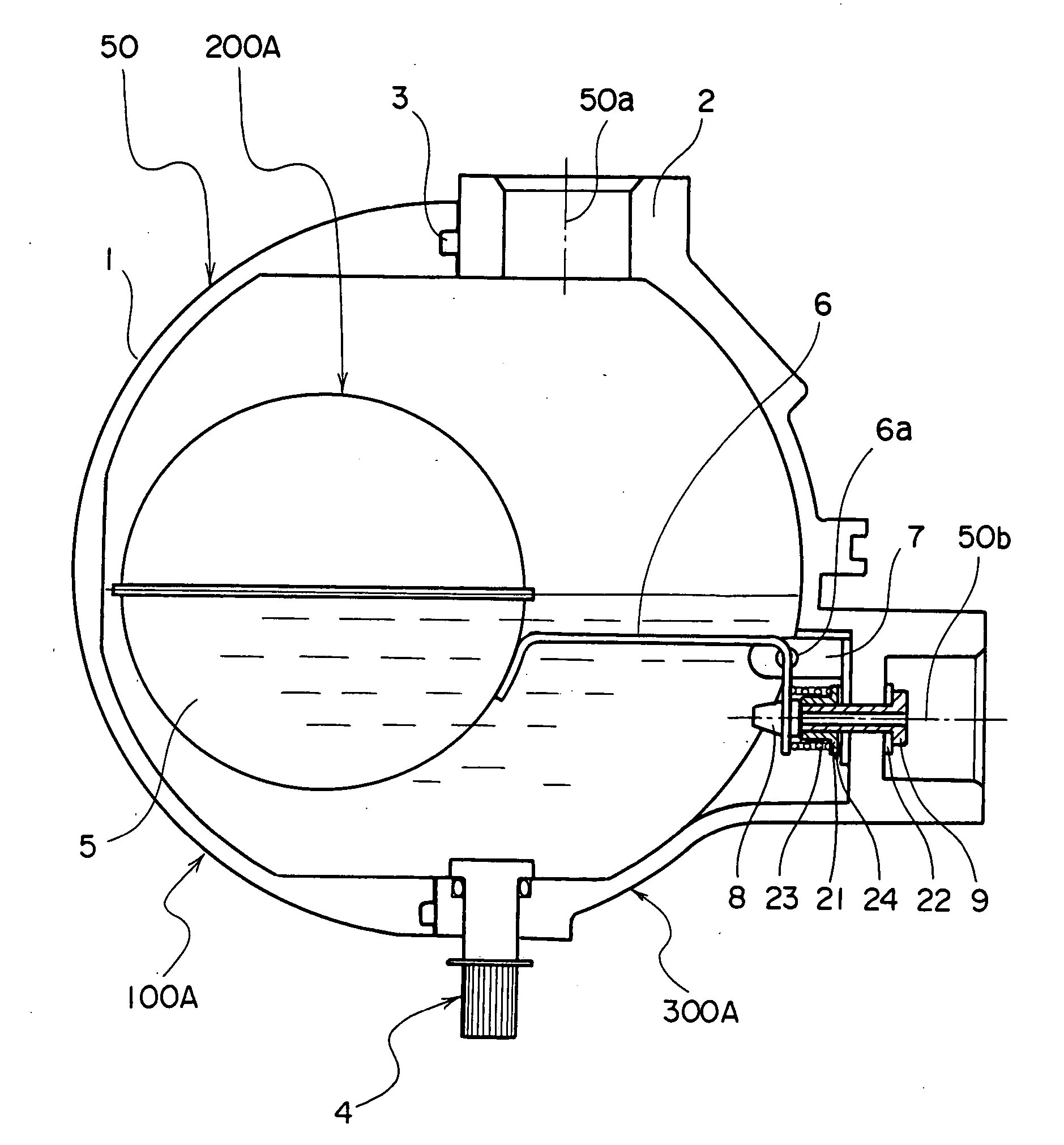
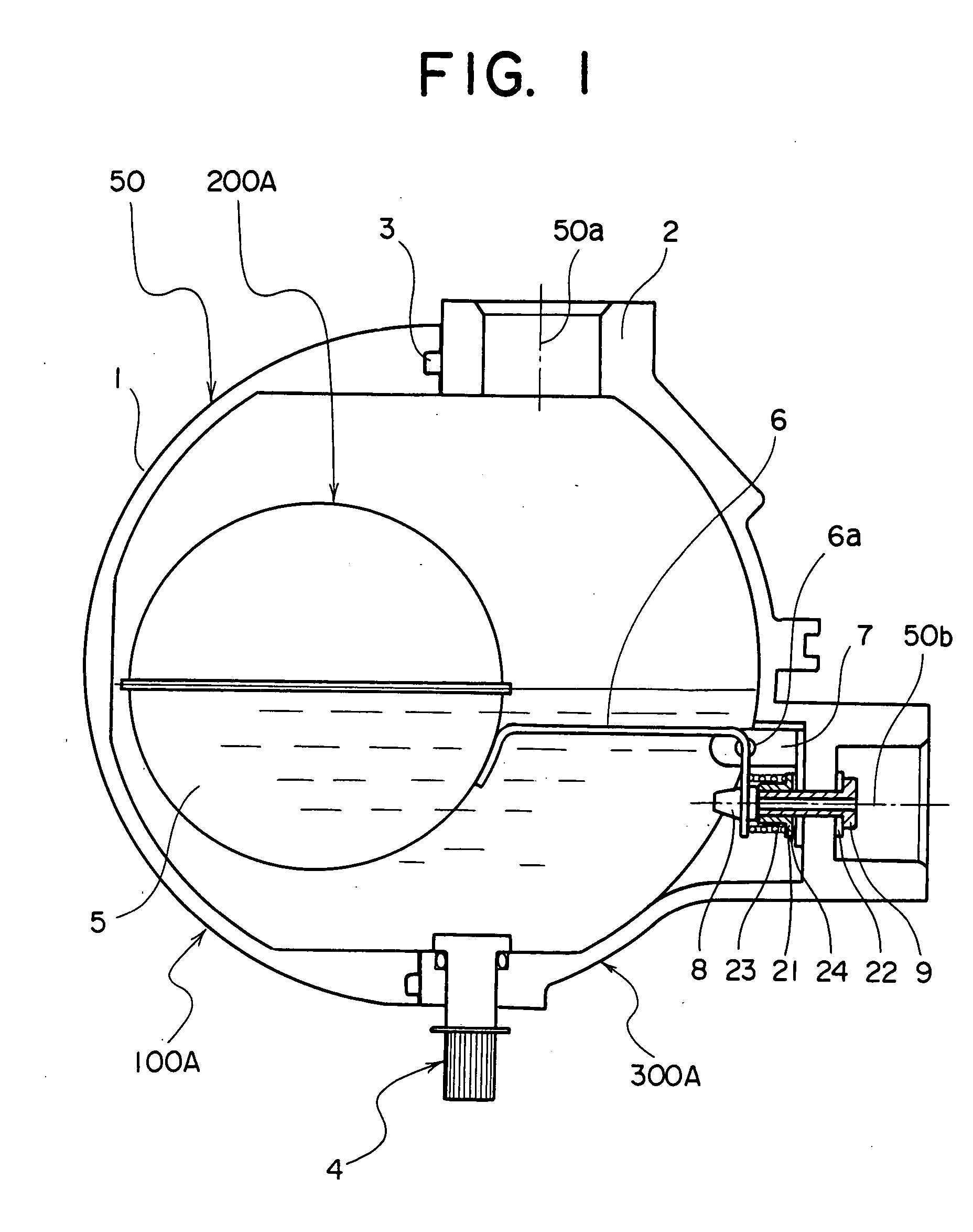
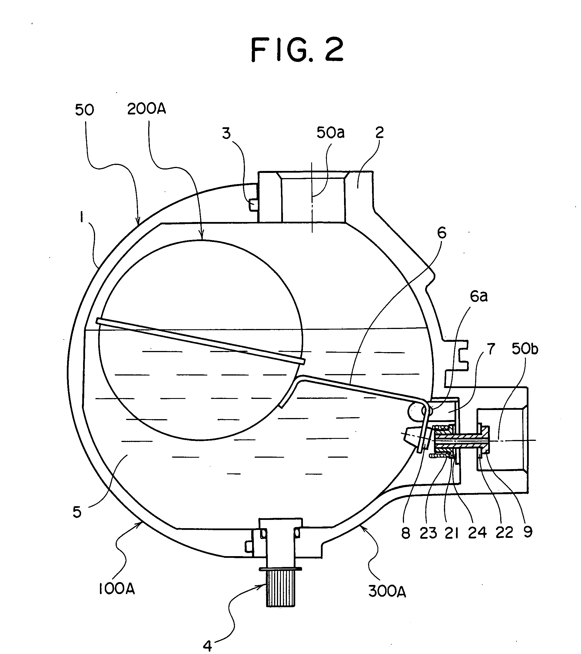
[0030] As shown in FIGS. 1, 2, 3, 4, and 7, reference symbol 300A indicates a drain trap which is composed of a case 10A, a float 200A, and a coil spring 23 serving as an auxiliary buoyancy device situated between the case 100A and the float 200A.

[0031] The case 100A is integrally formed by a case main body 50, a float bracket 7, a valve 9, an adjustment screw 21, an adjustment washer 24, a packing 22, and manual valve 4 equipped with an O-ring.

[0032] As shown in detail in FIG. 4, the valve 9 in this example is equipped with a flange, and the flange side of the valve 9 is situated on the outer side of the case main body 50 with the packing 22 therebetween. Further, the valve 9 is connected to the case main body 50 through thread engagement, and the other end thereof on the opposite side of the flange, that is, a screw portion protrudes into the case main body 50. The protruding portion has the adjustment screw 21 equipped with a flange, the flange side of the adjustment screw 21 b...

second embodiment

[0051] Referring to FIGS. 5 and 7, reference symbol 300B indicates a drain trap which is composed of a case 100B, a float 200A, and a compression spring 25 situated between the case 100B and the float 200A and serving as an auxiliary buoyancy device 25.

[0052] In this case, the case 100B is the same as that of the conventional technique as shown in FIG. 8, and the float 200A is the same as that of the first embodiment as shown in FIG. 1, so description thereof will be omitted.

[0053] Thus, the second embodiment differs from the first embodiment in that the compression spring 25 serving as the auxiliary buoyancy device is situated between the case main body 50 constituting the case 100B and the float main body 5 constituting the float 200A. Regarding the compression spring 25, one end thereof may be fixed to the case main body 50 with the other end thereof not being fixed to the float main body 5, so that when the float main body 5 rises due to the buoyancy F, the compression spring ...

third embodiment

[0065] Referring to FIGS. 6 and 7, reference symbol 300C indicates a drain trap which is composed of a case 100C, a float 200B, and a compression spring 23 situated between the case 100C and the float 200B and serving as an auxiliary buoyancy device.

[0066] In this case, regarding the case 100C, as shown in FIG. 6, instead of the manual valve 4 of the case 100A of the first embodiment of FIG. 1, there are provided a stay 16, a washer 18, a nut 19, a plate spring bracket 15, a fixation screw 17, and a plate spring 14; regarding the float 200B, instead of the arm 6 of the float 200A of the first embodiment equipped with the rotation shafts 6a, there is formed an arm 20 equipped with rotation shafts 20a; and further, there are added an adjustment screw 10, a nut 11, a magnet seat 12, and a magnet 13.

[0067] Thus, the third embodiment differs from the first embodiment in that, in addition to the force of FIG. 1, there is to be expected an suction force due to the magnet 13 and the plate...


PUM


Abstract

Provided are a drain water discharging method and a buoyancy type drain trap in which a float is accommodated in a case and drain water allowed to flow into the case can be discharged by buoyancy acting on the float. In a case where an inner diameter of the valve is increased in order to increase a discharge flow rate at a valve connected to an outlet port formed in the case, the movement of a valve seat for opening the valve is facilitated through addition of some force to increase the buoyancy or through a reduction in a weight of the float itself.

Description

BACKGROUND OF THE INVENTION [0001] 1. Field of the Invention [0002] The present invention relates to a technique of a buoyancy type drain trap, and more specifically, to a technique of discharging drain water accumulated in a drain trap by utilizing buoyancy with some force added thereto and by utilizing a suction force of a magnet. [0003] 2. Description of the Related Art [0004] As a conventional technique related to a buoyancy type drain trap, there is known a structure having a float 200A accommodated in a case 100B. [0005] In the following, the conventional buoyancy type drain trap will be described with reference to FIG. 8. [0006] In FIG. 8, reference symbol 300K indicates a drain trap composed of the case 100B and the float 200A. The case 100B is integrally formed by a case main body 50, a float bracket 7, a valve 9, an adjustment screw 21, a packing 22, and manual valve 4 equipped with an O-ring. Further, the case main body 50 is integrally formed by a first case 1, a second ...

Claims


Application Information

Patent Timeline
Patent Type & Authority Applications(United States)
IPC IPC(8): F16T1/20
CPCF16K31/24F16T1/24F16K33/00Y10T137/3068
Inventor SUGAWARA, TOSHIMI
Owner FUKUHARA KK
Why Eureka
Try Eureka